If I haven’t made it clear yet, I love Fallout. Love it. I’m not as big a fan of Fallout 76 for a variety of reasons that don’t belong on this blog, but it doesn’t stop me from appreciating the series’ 20+ year history of being stylishly committed to a retro-future apocalypse (unlike the present apocalypse, which is just viral and lame). Since I had a lot of time over Quarantine to re-work some parts of my home, I felt my shelves in my living room were looking a little bare, and decided I wanted to make some more Fallout props to adorn them.
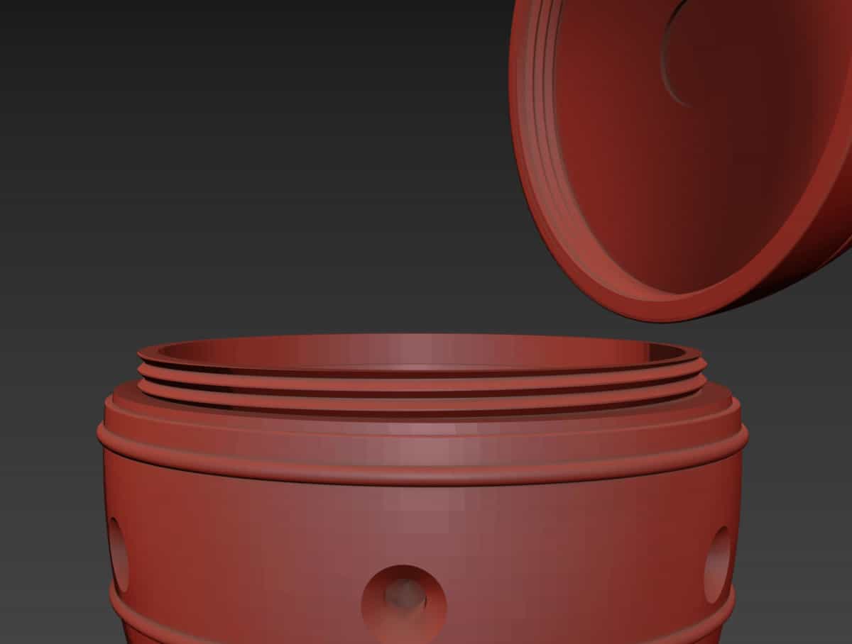
I stumbled onto these files for a Fallout 4 Mini Nuke Container posted by PowerHobo on Thingiverse and decided I’d give it a go, since my printers weren’t occupied with anything too pressing. The files are simple and straightforward, and I found myself thinking that since the nuke was essentially hollow anyway I could get away with putting whatever electronics bits I fancied inside.
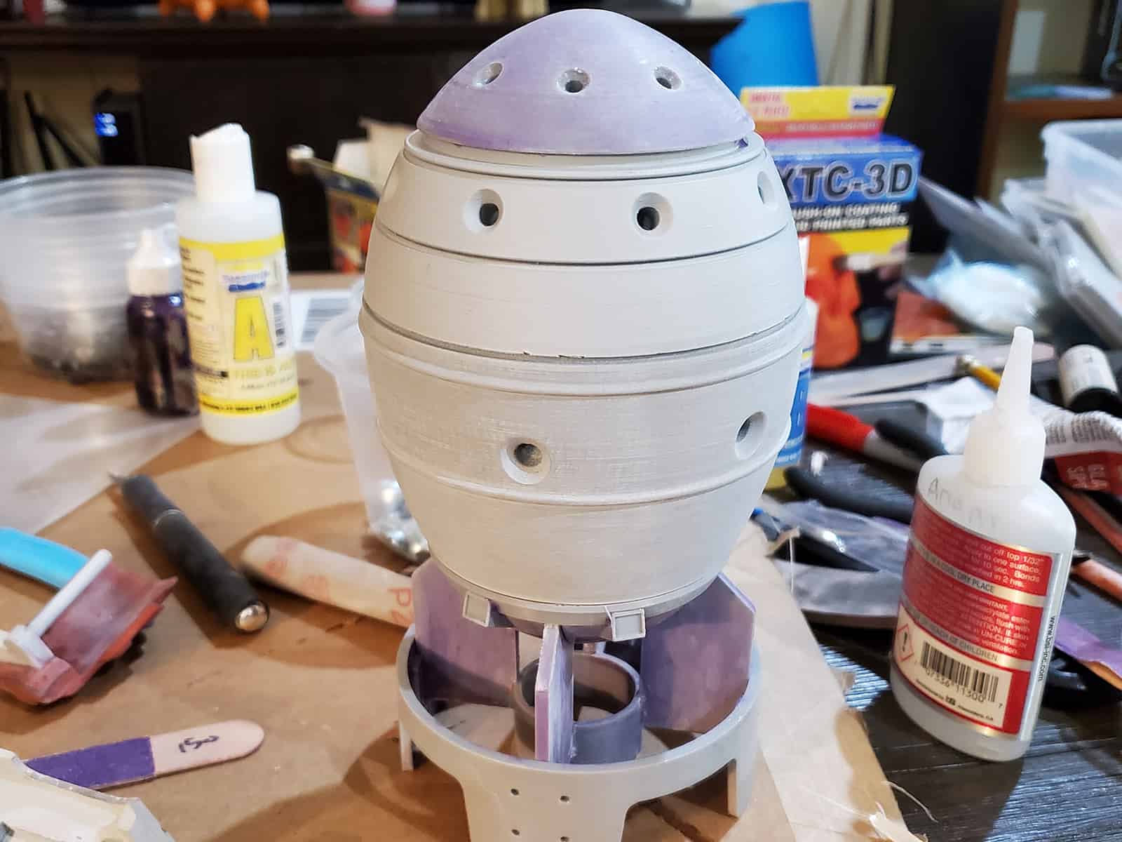
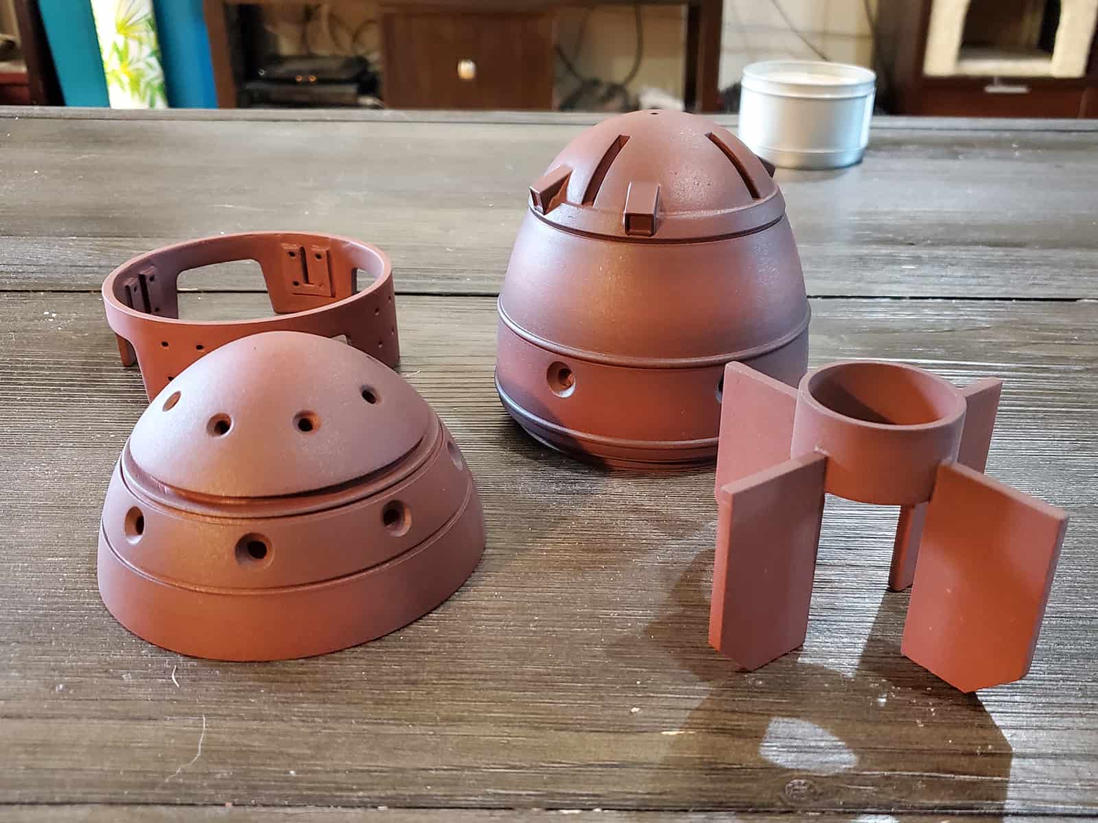
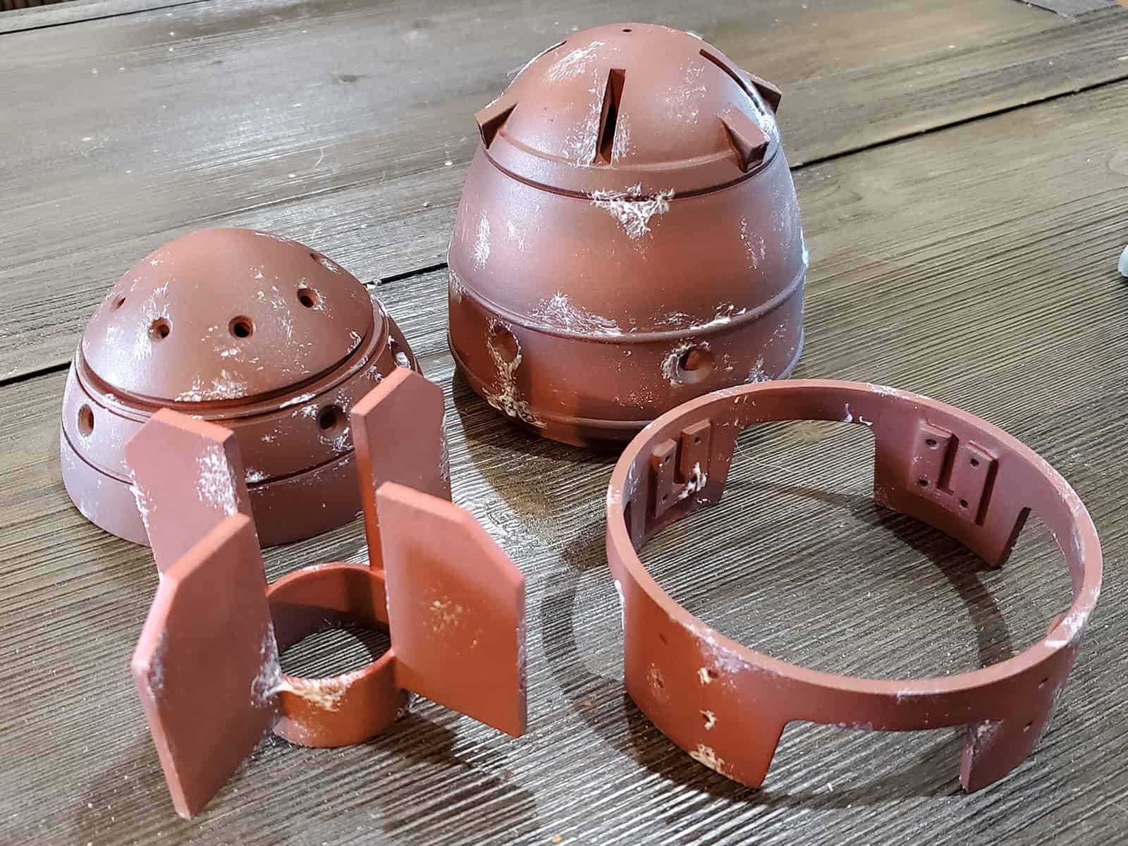
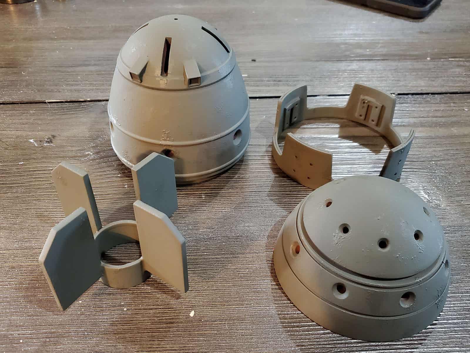
The parts printed very easily thanks to PowerHobo’s smart design work. If I had one critique at all, it might be that I’d have preferred the model to be a little higher resolution so that the round parts weren’t quite as faceted. Still, that’s something relatively minor, and can easily be corrected by a bit of post-print sanding, which is exactly what I did.
I spent a bit of time watching some footage of the Super Mutant Suiciders in-game running around with these mini-nukes. I decided I wanted to do lights and sound on this one, but I also opted to keep it simple and cheap. The sounds mostly consisted of a chirping warning beep and a rising sort of siren sound effect that repeated, and the lights looked to be a set of four blinky red guys at the front of the nuke where some of the screw holes might be. I went for a cheap little piezo buzzer as my sound source and decided I’d simply program an arduino to make the audio effects in a manner similar to how I’ve done things like my Data Knife.
This was with an Adafruit 5V Trinket and a 5V Piezo Buzzer, though the final prop ended up using a 3V Trinket instead. It took a bit of trial and error to get something close to what I was after, but I think it’s pretty clear what it’s trying to emulate. I’m sharing the code here for anyone who might be interested in trying to do this, themselves:
#ifdef __AVR__
//#include <avr/power.h>
#endif

#include <elapsedMillis.h>

// The notes below are defined as frequencies here just for reference.
// You could always change these if you wanted.

#define C7 2093
#define CS7 2217
#define E7 2637
#define FS7 2960
#define G7 3136

#define LEDPin 3

volatile uint32_t toggle_count = 0; //used in the sorcery that makes the TrinketTone() function go.
int freq = 0;
int power = 255;
elapsedMillis timer;
elapsedMillis sirenTimer;
elapsedMillis chirpTimer;
bool chirping = false;
int sirenDuration = 4800;

void setup() {
  //startChime(); //plays the initializing chirp.
  pinMode(LEDPin, OUTPUT);
}

void loop() {
  if(timer >= 800){
    timer = 0;
    chirpTimer = 0;
    chirping = true;
  }
  TrinketTone(sirenTimer/3.5, 40);
  if(chirping){
    chirp();
  }
  if(sirenTimer > sirenDuration){
    sirenTimer = 0;
  }
}

void chirp(){
  if(chirpTimer <= 40){
    TrinketTone(800, 40);
    analogWrite(LEDPin, 255);
  } else if (chirpTimer >40 && chirpTimer <= 80){
    TrinketTone(900,40);
    analogWrite(LEDPin, 200);
  } else if (chirpTimer >80 && chirpTimer <= 120){
    TrinketTone(1200,40);
    analogWrite(LEDPin, 150);
  } else if (chirpTimer > 120 && chirpTimer <=160){
    TrinketTone(750, 40);
    analogWrite(LEDPin, 100);
  } else if (chirpTimer > 160 && chirpTimer <= 200){
    TrinketTone(700,40);
    analogWrite(LEDPin, 50);
  } else if (chirpTimer > 200 && chirpTimer <= 240){
    TrinketTone(1350,40);
    analogWrite(LEDPin, 0);
  } else {
    //freq += 6;
    chirpTimer = 0;
    chirping = false;
  }
}


void startChime() {
// Just something that sounded decent for a
// 'switched on' sound effect through my piezo.
  TrinketTone(CS7, 75);
  delay(30);
  TrinketTone(E7, 75);
  delay(30);
  TrinketTone(FS7, 75);
  delay(30);
  TrinketTone(G7, 75);
  delay(150);
  TrinketTone(CS7, 15);
  delay(20);
  TrinketTone(CS7, 15);
  delay(20);
  TrinketTone(CS7, 15);
  delay(20);
  TrinketTone(CS7, 15);
  delay(20);
  TrinketTone(CS7, 15);
  delay(20);
  TrinketTone(CS7, 15);
  delay(20);
}

/* The Trinket and its ATTiny85 processor cannot, by default, use the arduino tone() library.
 * This is a huge pain in the ass. However, Bruce E. Hall of www.w8bh.net is a brilliant dude
 * and has made my life immeasurably easier by providing a TrinketTone() function and some
 * basic ISR timer stuff that runs at some higher hardware level than I genuinely understand.
 * Needless to say, it works, it's small enough to fit on the trinket, and I am grateful as hell.
 * http://w8bh.net/avr/TrinketTone.pdf and http://w8bh.net/avr/TrinketTimers.pdf are great resources.
 */

void TrinketTone(uint16_t frequency, uint32_t duration) {
  // scan through prescalars to find the best fit
  uint32_t ocr = F_CPU / frequency / 2;
  uint8_t prescalarBits = 1;
  while (ocr > 255)
  {
    prescalarBits++;
    ocr /= 2;
  }
  // CTC mode; toggle OC1A pin; set prescalar
  TCCR1 = 0x90 | prescalarBits;

  // Calculate note duration in terms of toggle count
  // Duration will be tracked by timer1 ISR
  toggle_count = frequency * duration / 500;
  OCR1C = ocr - 1; // Set the OCR
  bitWrite(TIMSK, OCIE1A, 1); // enable interrupt
}

ISR(TIMER1_COMPA_vect) {
  if (toggle_count != 0) { // done yet?
    pinMode(1, OUTPUT); //if it's already in Output mode, nothing happens, tone continues.
    toggle_count--; // no, keep counting
  } else { // yes,
    pinMode(1, INPUT); //switching the pin to Input immediately stops the tone signal.
  }
}
I like using the ElapsedMillis library with these kinds of projects because it honestly makes working with timers brainlessly easy. As I have mentioned in the past, the Trinkets don’t have native support for the tone() function, but Bruce E. Hall has written a little code snippet that achieves basically the same thing on pin 1 of the Arduino. I’ve got Pin 3 set up to simply make the red LEDs I’m installing flash in time with the chirping of the nuke.
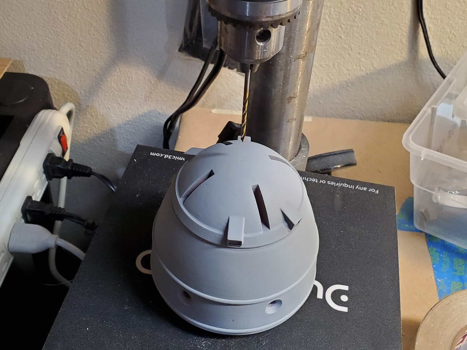
I hadn’t planned on doing this audio stuff at the outset, or I would have modeled a hole for the piezo into the body of the bomb. Still, 3D-printed plastic is not hard to work with, and I chucked the parts under my drill press to widen enough of a hole out to snugly fit the piezo in.
I opted to put the piezo on the bottom of the bomb, where the fins were, because I thought it’d be easier to disguise there.
I started debating how I wanted the prop to be able to turn on and off. A simple push-button toggle or something would work fine, but I didn’t see anywhere I could hide it very easily without ruining the bomb’s aesthetic. Luckily, I had a little brain-wave of inspiration and realized that the bomb was already designed to twist – that is, for the cap to rotate on the body of the bomb so you could remove it or screw it on if you wanted to.
With this arrangement, it wouldn’t be too hard to rig up something that would turn the bomb on (or ‘arm’ it) if you twisted the cap. I had a bunch of leftover magnetic reed switches from another project that made this pretty simple – these ones in particular are ‘normally closed’, which means that they allow electricity to pass unless they’re subjected to magnetic forces, which separate the leads on the inside of the switch and cut power. By positioning a magnet in the right spot on the inside of the lid, I had a simple way of cutting off the battery from the Arduino.
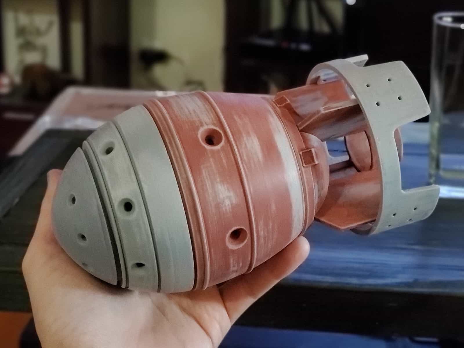
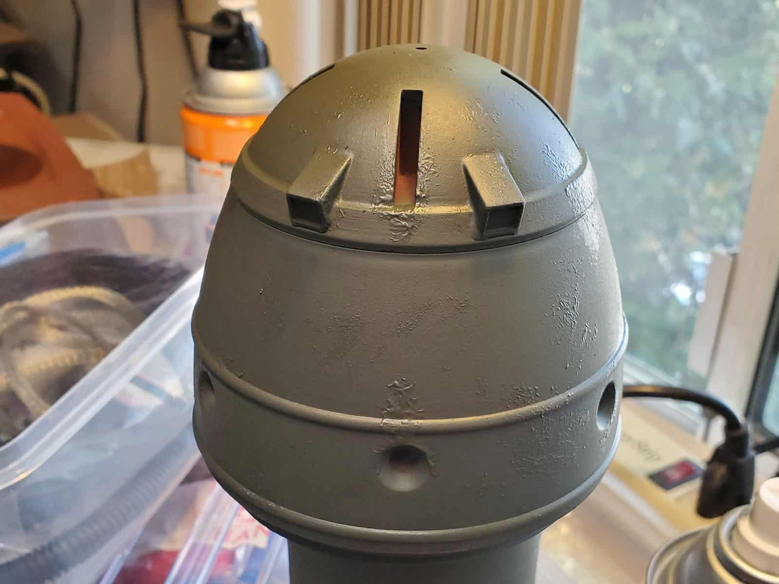
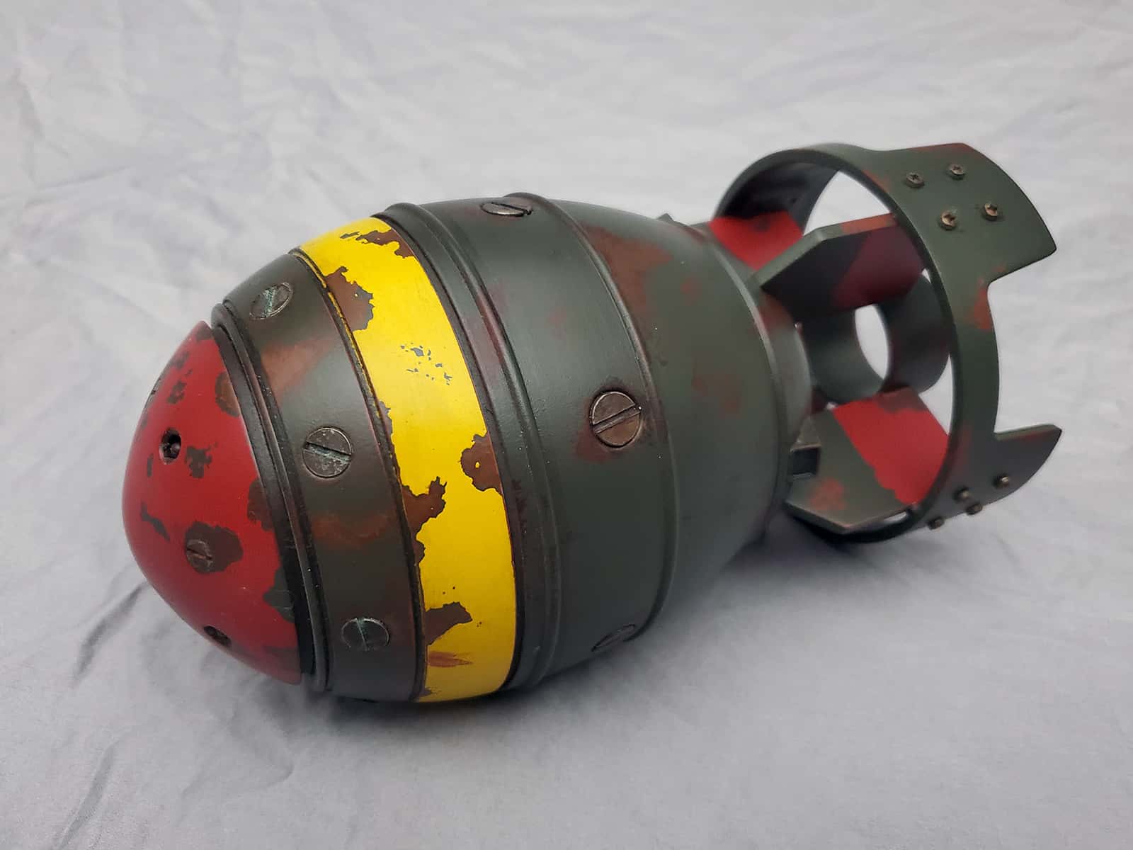
With that taken care of, I wanted to tackle painting the nuke next – I felt like it’d be easier to put the LEDs and stuff in at the end, rather than trying to paint around them or mask them off. I wanted a weathered look similar to what you’d encounter in the Fallout games, so I started off by using a rust-red primer and toned it here and there with another matte brown spray I had laying around. Airbrushing it to get some tonal differences would also be an option.
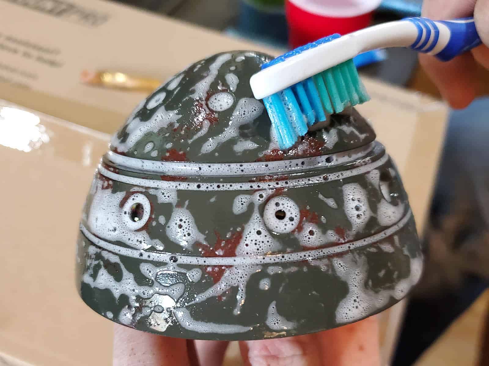
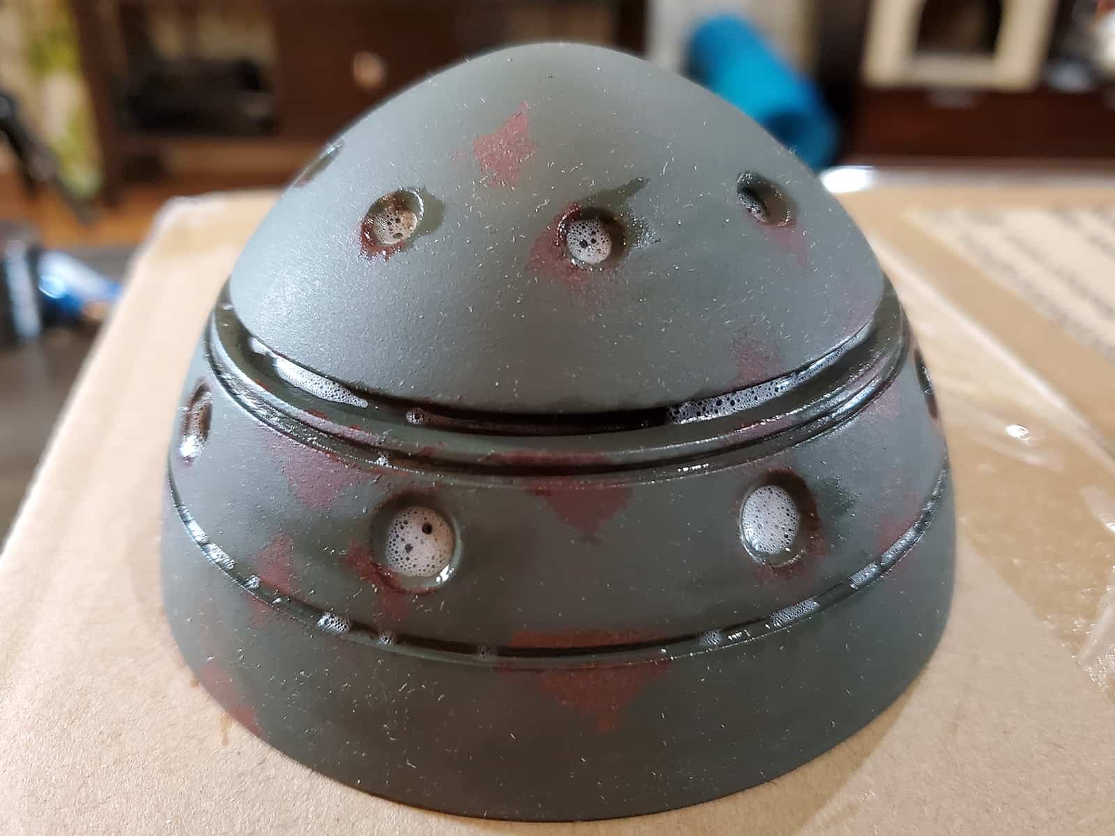
I went over this with a Matte Wheel Clearcoat which I’m currently fond of to help lock in the rusty color beneath everything else I was about to do. Once that dried, I got a fine-tipped paintbrush and some toothpaste and started applying it liberally around the areas on the bomb that I thought should remain rusty. The toothpaste in this instance acts as a mask for any paint that’s applied overtop. I had a can of Deep Forest Green Camouflage spray paint from another project in my workshop that fit what I needed pretty nicely, so the bomb parts all got a solid coat of it over the toothpaste. Once that had time to fully dry, I rinsed the parts off in the sink with warm water (not too hot, because you don’t want to warp the plastic) while scrubbing it down with an old toothbrush.
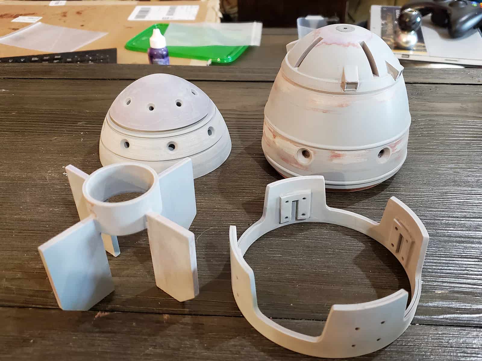
It worked pretty nicely, and it’s an easy technique. If you really want to sell the effect, you can go in with a fine brush and try to highlight the edges of where the paint and rust meet with a lighter olive color, which helps add the illusion of depth to the peeling paint.
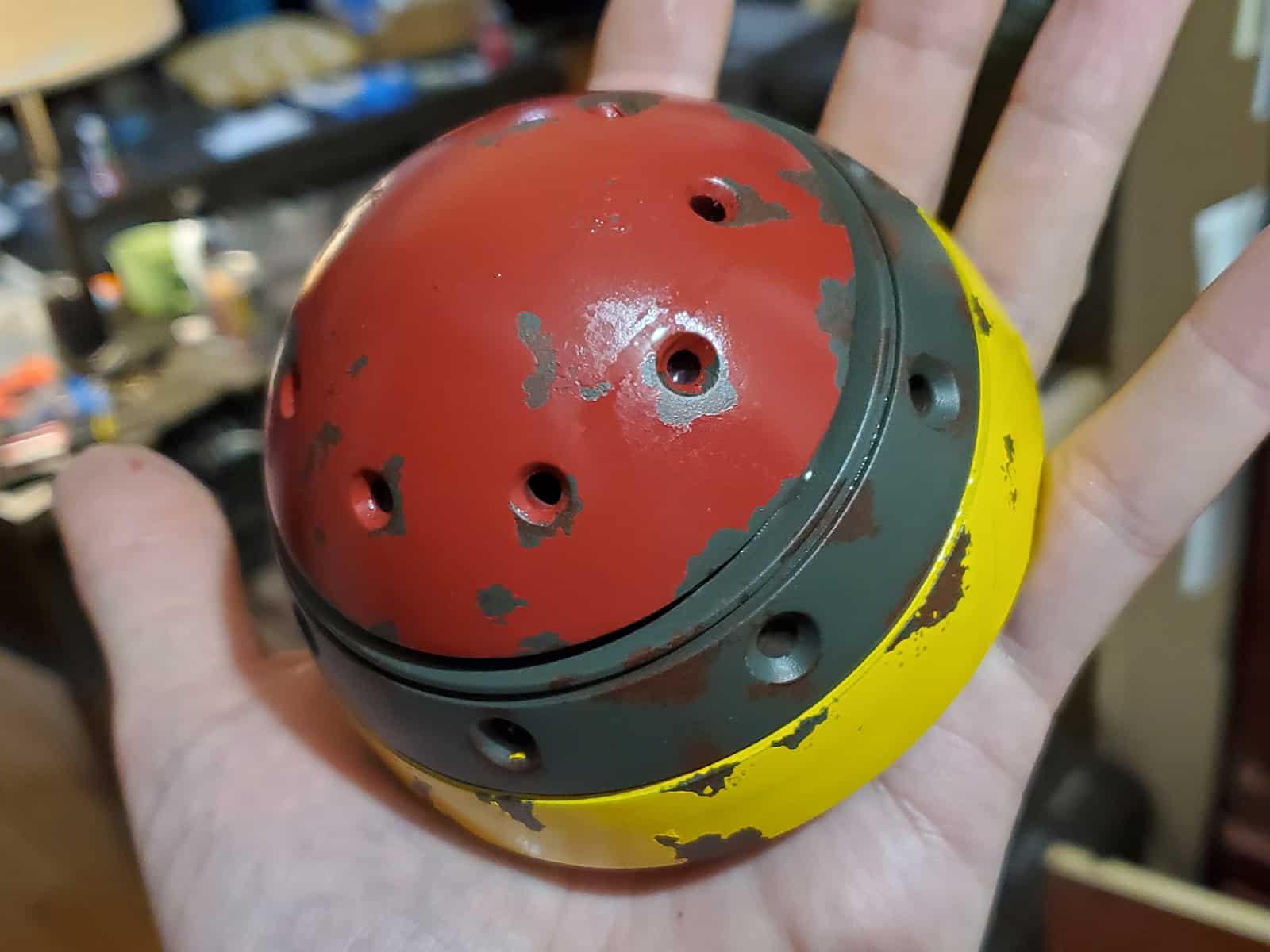
The bomb had a few other colors that needed to get applied, so I clear-coated the parts between each color step to make sure I wasn’t scrubbing off more paint than I intended. The other colors went down pretty much the same way – I put toothpaste on areas where I wanted the paint to be chipped, masked the rest of the bomb with tape, sprayed the colors, and rinsed the toothpaste back off.
With the parts all painted up, I went ahead and installed the electronics more permanently. I drilled four of the screw-holes at the top (red) portion of the bomb out to embed 3mm LEDs, and routed the cables through to the bottom of the inside lid. The arduino was simply hot-glued to the bottom of the bomb’s interior, and I used cyanoacrylate superglue to permanently affix the magnetic reed switch and a neodymium magnet to the inside rims. For power, I opted to use an 18650 battery, since they’re rechargeable and I had a bunch of them in my workshop. These are the kind of things that you might see being used in vape rigs. They’re only around 3.7V, so I switched from using the 5V Trinket I had been testing with to a 3.3V one instead, but I didn’t notice any negative consequences with the piezo or other hardware.
I should mention that PowerHobo’s model on Thingiverse does include 3D-printable screws and other hardware, but I didn’t use them. I have enough random screws and bolts kicking around my workshop that it wasn’t too hard to find things that were about the right size to fill the holes in. I screwed them directly into the 3D-printed plastic (with a bit of superglue on the threads) and used a bit of solution called Black Max that I had from another project to oxidize the top surfaces of them a bit.
That’s it! Thanks to PowerHobo for sharing his model, and I hope that this helps someone who might be interested in making their own little nuclear football.


