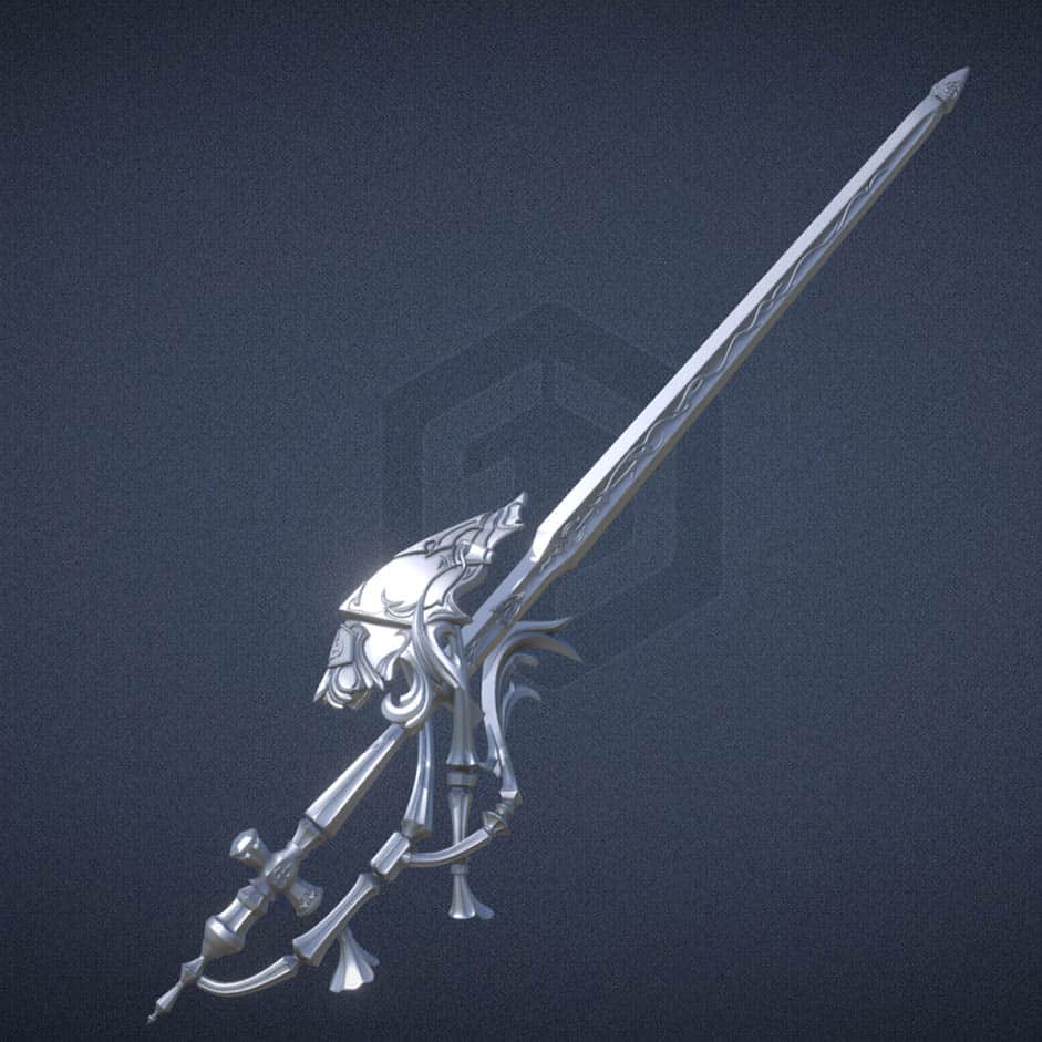
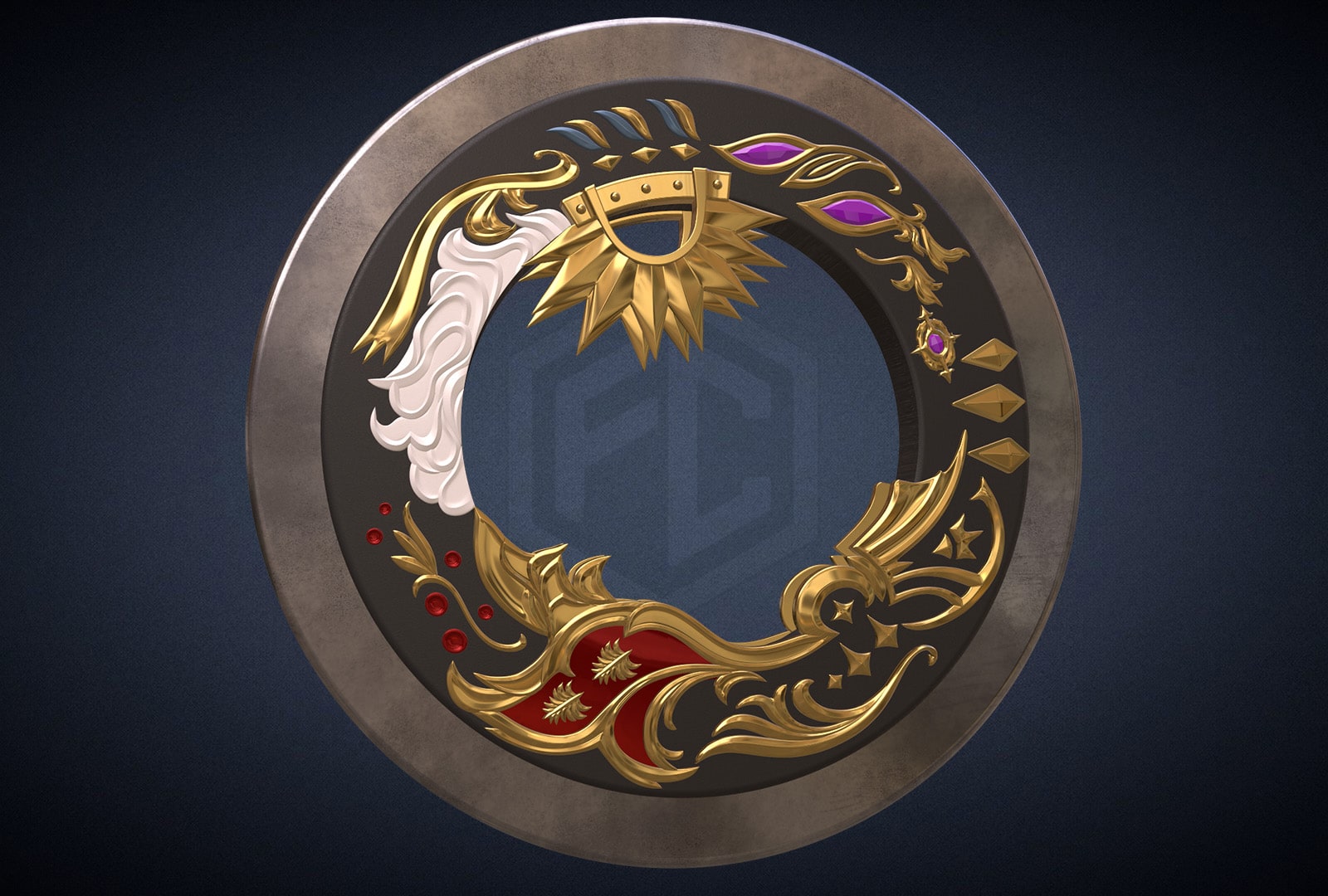
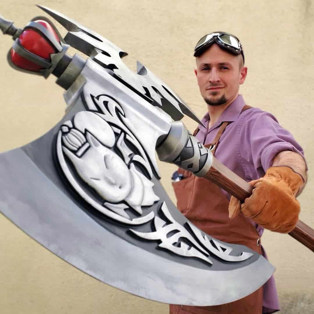
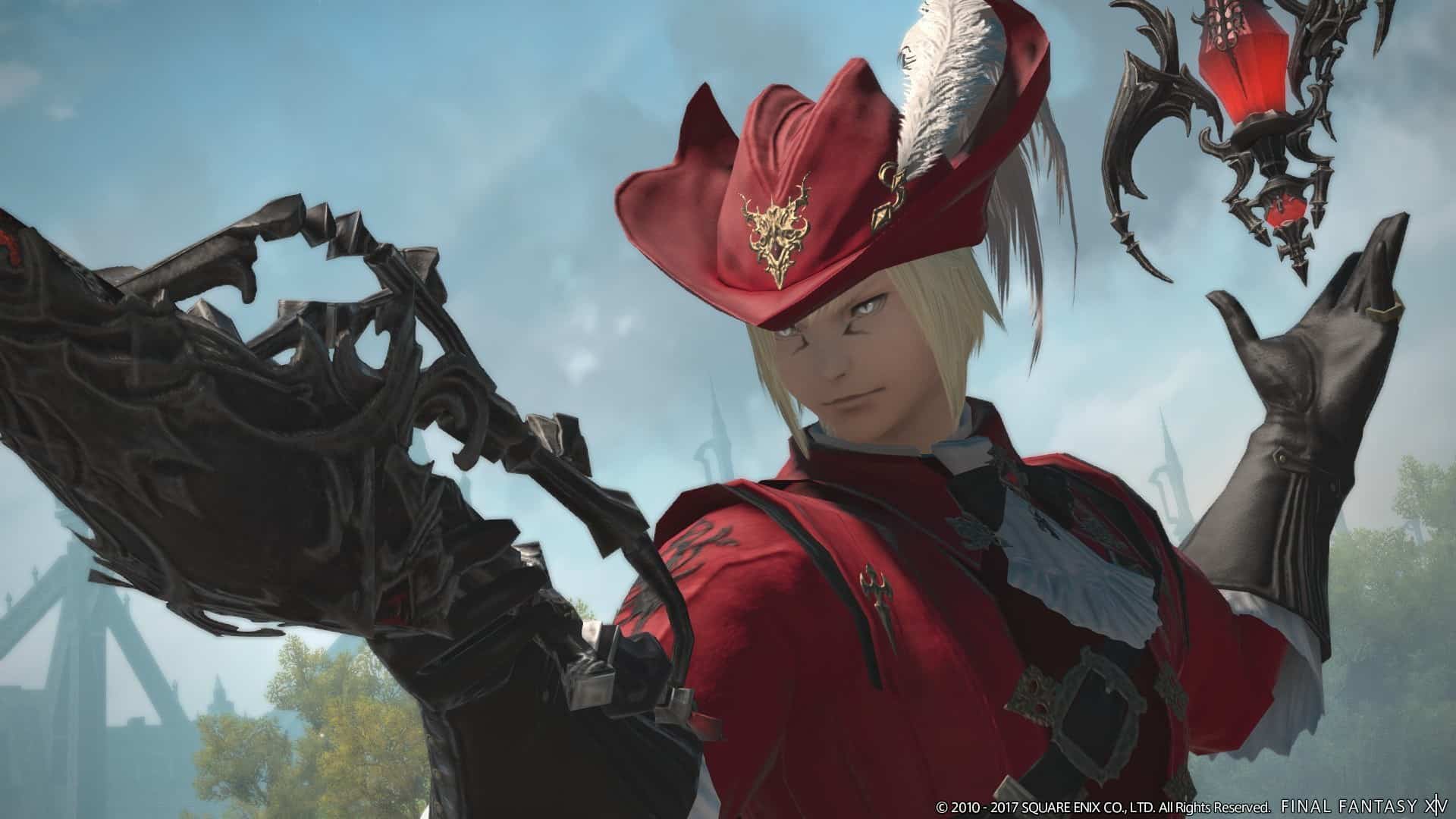
We were presented with the fun-yet-daunting prospect of recreating the Antiquated Murgleis from Final Fantasy XIV. This weapon (and the orb that pairs with it) is the signature equipment of the Red Mage class from that game, and is used prominently by both players and NPCs. It’s a hilariously impractical-looking thing, and I love it for just how much it embodies what Final Fantasy is.
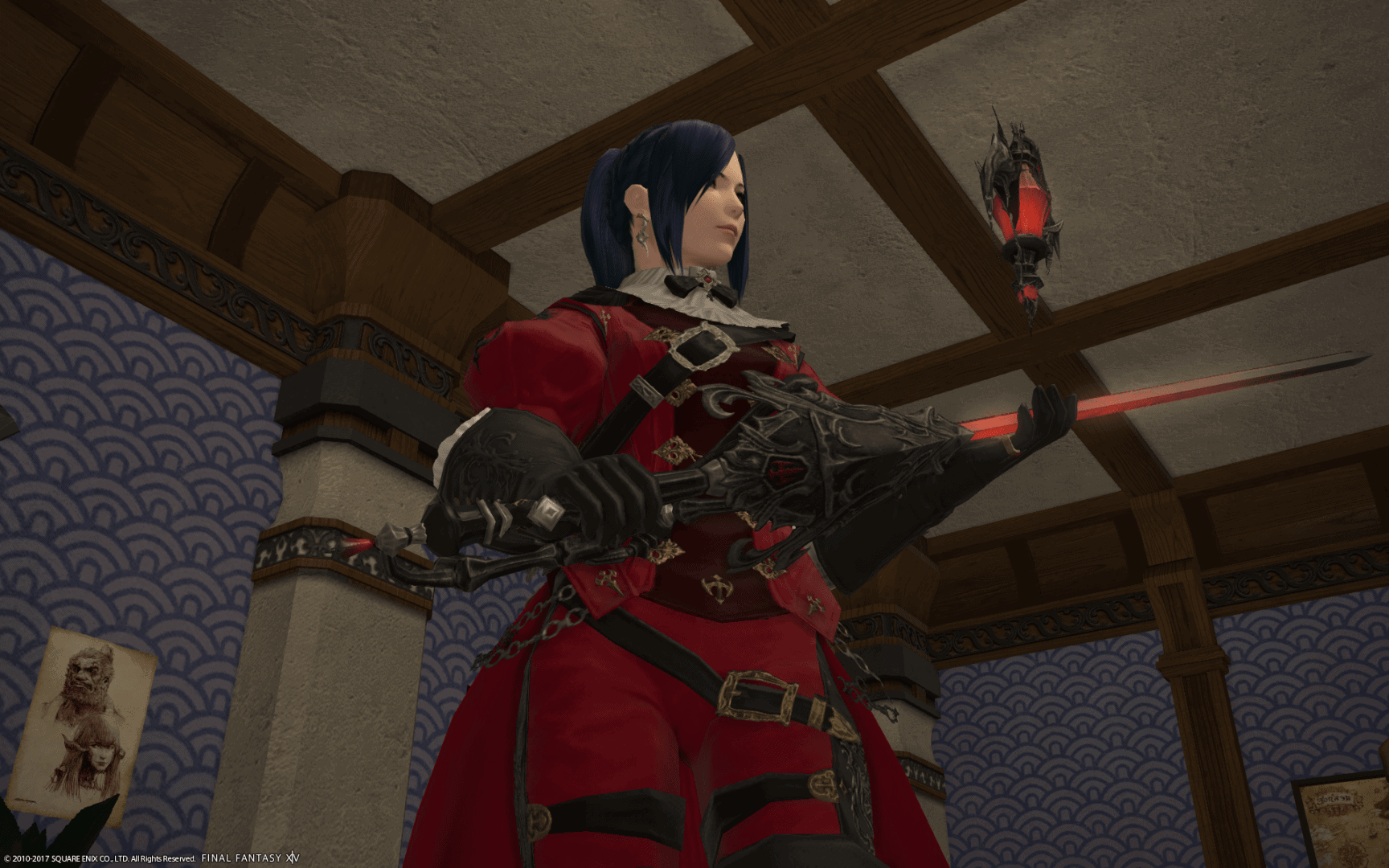
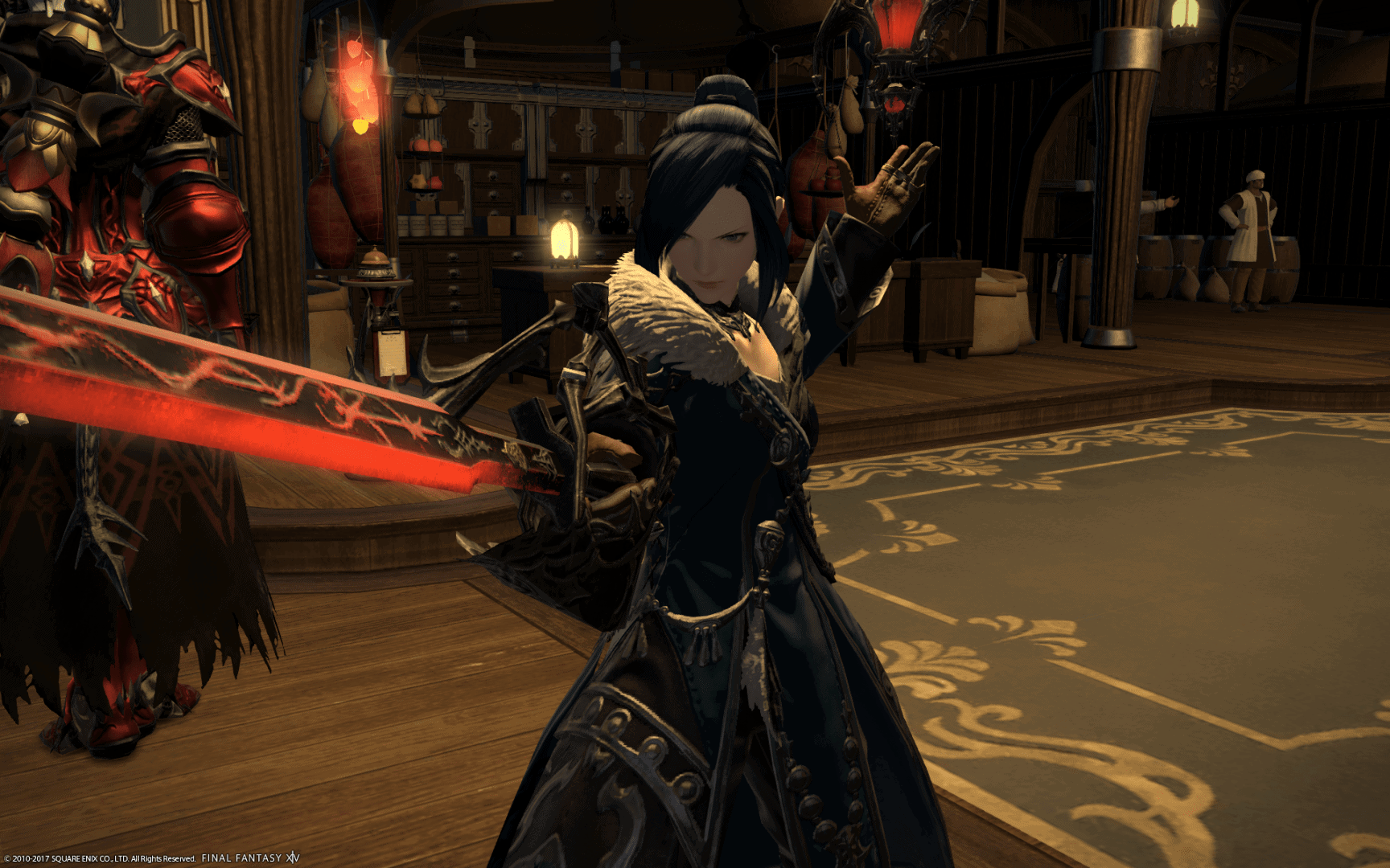
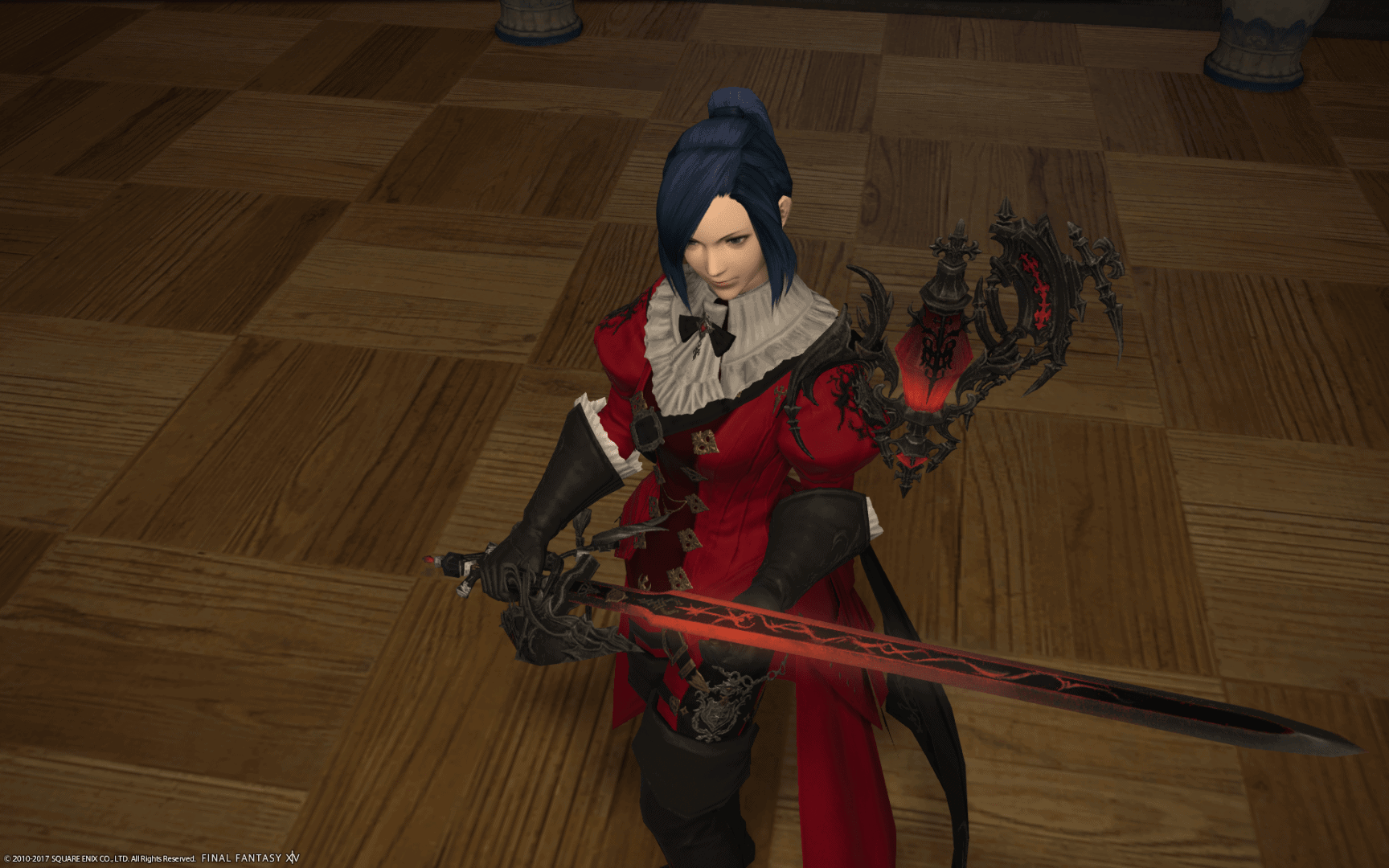
At the start of the project, the client provided us with a bunch of reference images for review, most of which were from in-game screenshots.
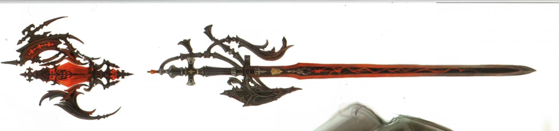
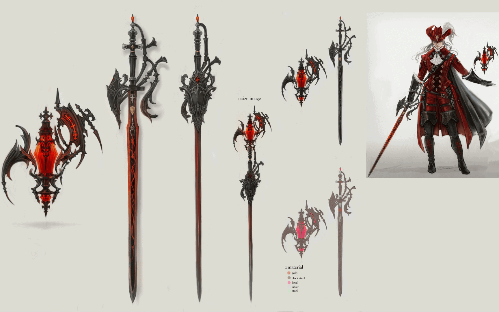
We were also provided some concept art of the weapon in the form of some scanned materials from the art book for the game.
The scan is a bit fuzzy, but does help elaborate on some of the necessary details.
Before we started, we were given a few specifications for the project which made designing things a bit more challenging. The sword is intended for use and showcasing at conventions, and therefore has to be ‘con-safe’. It may have to pass through metal detectors or other security checks. Because of this, the client wanted us to avoid using metal parts in the construction of the prop. Given that the proposed length of this thing was about four and a half feet from end-to-end, my usual approach would have been to reinforce the core of the prop with something rigid and strong, like a strip of thick aluminum down the blade and through into the handle. Without this sort of reinforcement, there would be little hope that the blade would be sturdy enough for its intended use.
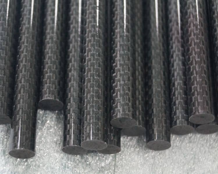
We brainstormed a few options and ultimately settled on carbon fiber rods. These rods are strong and rigid. They are surprisingly lightweight, and most importantly, they are not going to trip a metal detector. Based on what I’ve read about them, it looks like their primary use is as supports for performance kites. I ended up buying them in two different diameters – a set of 5mm, and a set of 2.5mm. They are available in 1-meter lengths, which hilariously isn’t long enough to actually reach through the entire length of the sword, but they do the job of connecting the blade sections and handle nicely.
I will note that the diameters listed on the carbon fiber rods are not as exact as I would have liked. Some areas along the length of the 2.5mm rod were as thick as 2.7mm, which meant that I had to spend some time sanding the rods down and drilling the holes they were meant to go through a little bit wider. Not a big deal, but something to know for next time.
In addition to the prohibition against metal, the client wanted us to try and keep the weight of the finished product as light as possible. We discussed the possibility of making the sword out of lightweight materials like foam or urethane. The unfortunate issue with those materials is that they require the making of a mold of the basic sword shape prior to production. We absolutely could have done that, but the cost of mold rubber and jacketing materials for such a huge prop would have ended up adding hundreds of dollars to the cost of the finished item, and the client in this case did not want to go that route.
Instead, we ended up approaching this as yet another 3D printing project. When you print a model, you can set parameters for how thick the ‘skin’ or outer surfaces of the model are. You can also adjust infill all the way from hollow to completely solid. The client settled on an approach where the sword would be printed in PLA plastic, and we would adjust the infill levels as necessary and appropriate in order to minimize wasted weight. Once the entire prop was printed, it’d be assembled, sanded down, and coated in a layer of XTC-3D. This epoxy usually does a pretty good job of not only smoothing the surfaces of a 3D print, but reinforcing the outer shell of the part.
We discussed the possibility of including some practical effects in the project because, quite frankly, I thought it’d be awesome to make the blade and orb actually glow. The options for this unfortunately didn’t fall in the client’s budget or desires this time around, but I’m entertaining the idea of making one in future as a proof of concept anyway, as I’ve been wanting to make some glowing swords from The Witcher series. As a compromise, we agreed to try mixing strontium aluminate (or other similar UV-reactive material) into the paint, which may yield a comparable effect.
With all of these details out of the way, the smartest place to start on a prop from a game is to see if you can get the game files directly. I downloaded a trial of the game, and it didn’t take long to find a tool to start pulling assets out.
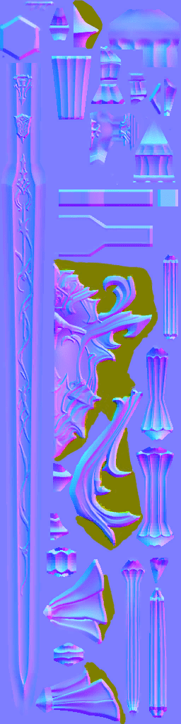
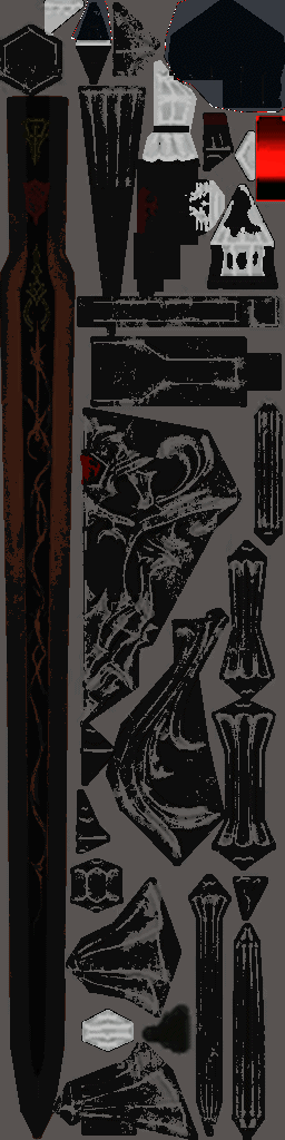
This thing is lacking in a lot of details, but it’s still great to have something to work from. Using the base mesh like this ensures that I have something to check my sense of scale and proportion against while I model. The mesh itself gets away with murder thanks to the use of textures to handle things like bump mapping or transparency. Interestingly, the textures I was able to export were not particularly high-resolution. They maxxed out at 256 x 1024, and were fairly low quality.
I dragged them into Photoshop and did my best to clean up and sharpen what details I could. The opacity map was missing entirely, so I made a quick and dirty replacement from the normal map.
When you compare the model I had to work from to what appears in-game, the difference is fairly stark. I’m still not entirely sure I understand what rendering magic the game uses to produce the higher-quality results visible in the reference images I was provided. It might be that the texture maps I was able to export were just lower-resolution versions of what’s actually in use, but I never found anything better.
MODELING
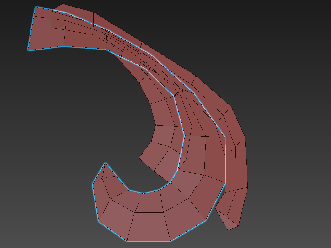
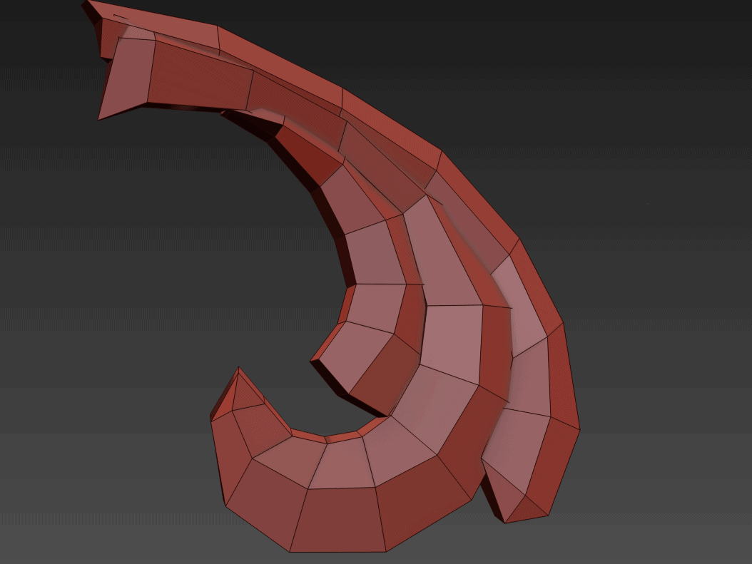
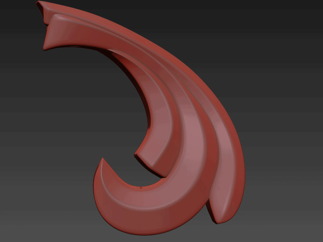
Without a doubt, this project has been stretching the limits of what I knew how to do in 3D Studio Max. I’ve learned a lot from banging my head against this mesh. The wrought-iron-railing look to the handle and quillions was one of the first things I tackled. I found that the easiest way to get predictable, repeatable results was to put together low-poly geometry and lean heavily on 3D Studio’s Open Subdivision modifier, which interpolates higher-detail contours based on certain rules that you set up. These rules are primarily controlled on an edge-by-edge basis with the crease parameter, which basically lets you tell the application which edges should remain hard versus ones that should be smoother or more contoured.
I don’t doubt for a second that there might be easier ways to approach this problem, but I liked this because if I needed to make changes, I could always just drop back down into the low-poly geometry and tweak things. If you delete edges the whole thing falls apart and you have to manually reassign edge weights to the part again, but overall it got me to the quality I was looking for in a 3D printable mesh. The main length of the handle and sword were the first parts of the project I tackled this way, and gave me an opportunity to get my feet back under me with using 3DS Max.
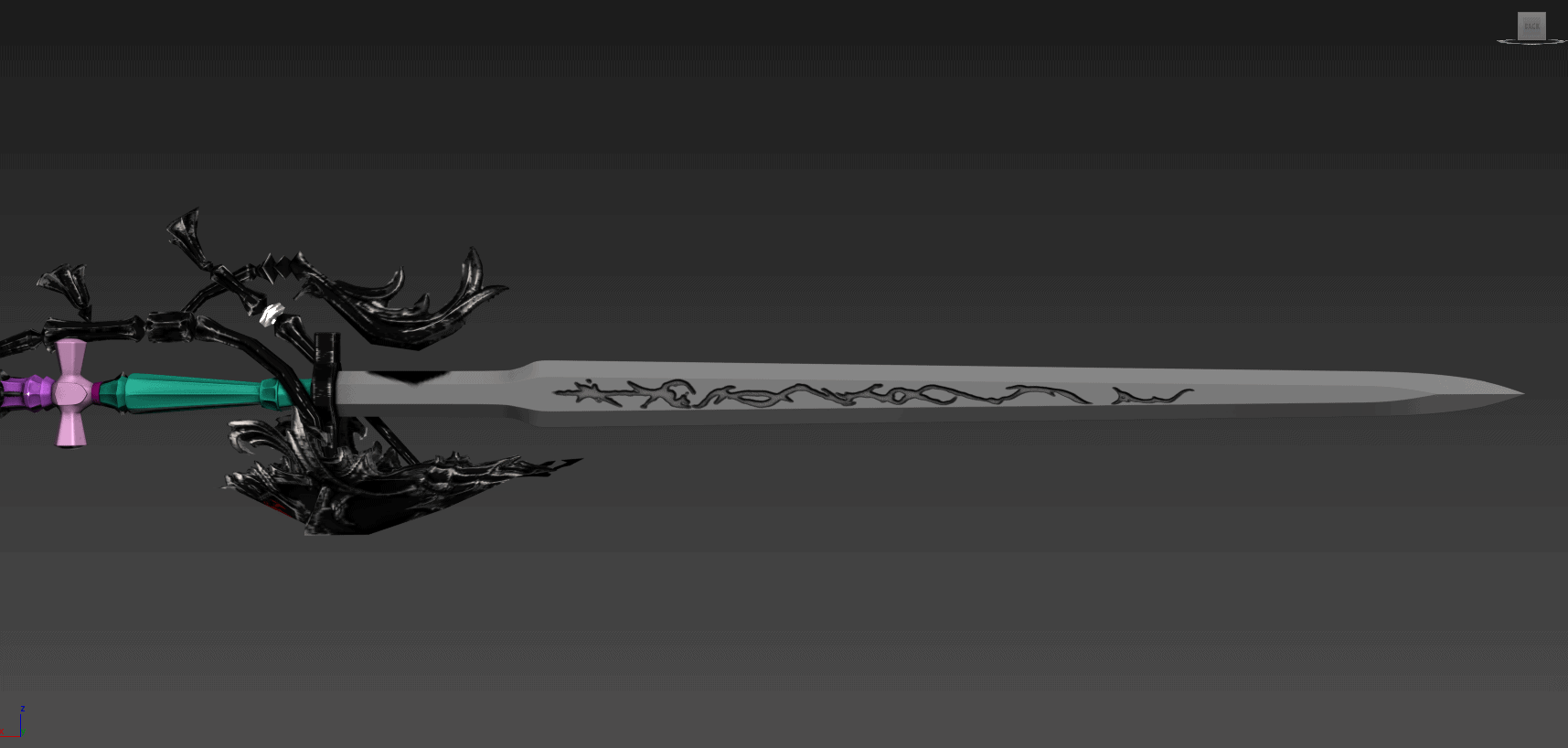
The blade ended up being about 40″ long just by itself. Like a lot of parts on this model, we ended up making and re-making it multiple times as our client reviewed it and as better reference material became available. The ‘first draft’ of the blade had the rune details somewhat crudely etched along the flat of the sword in zBrush.
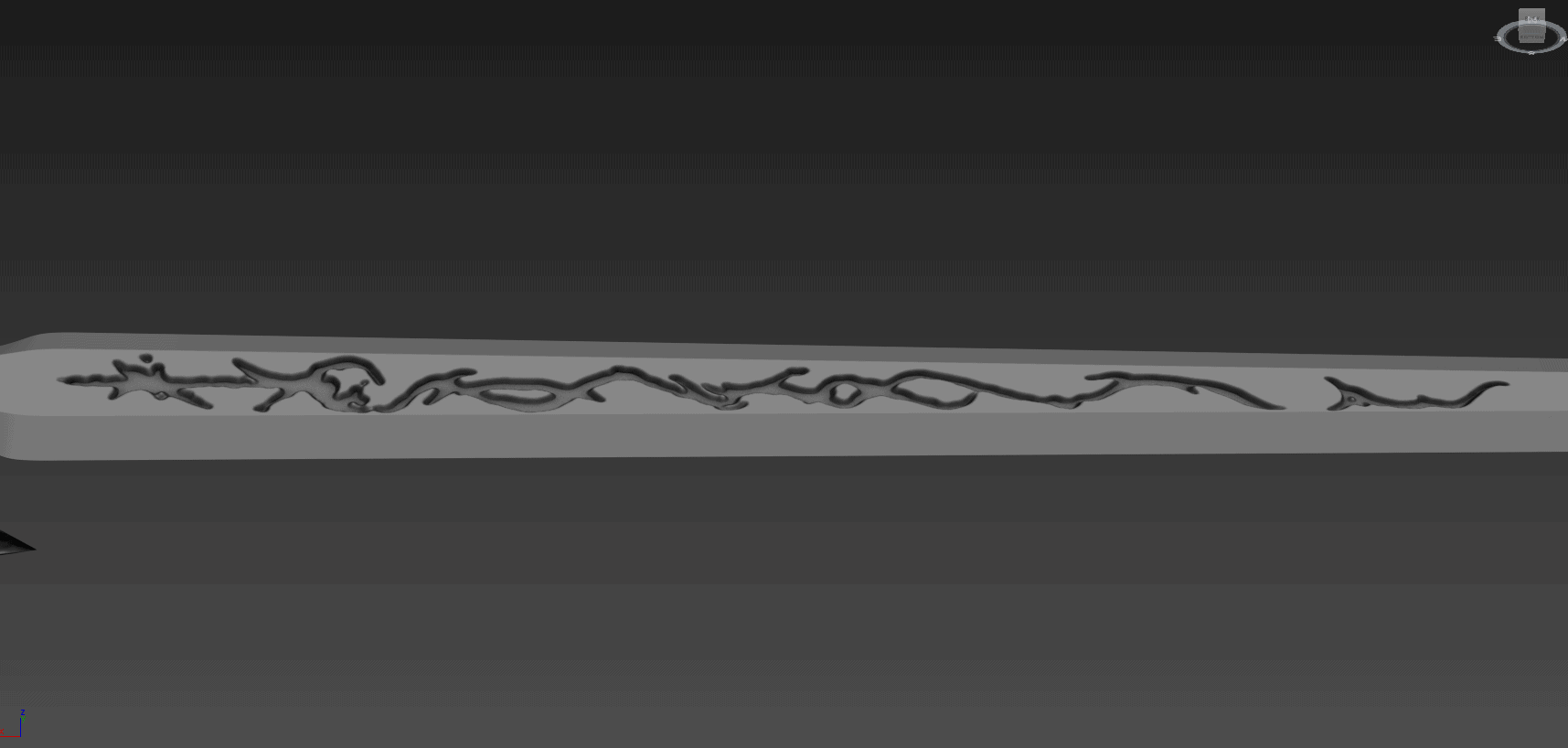
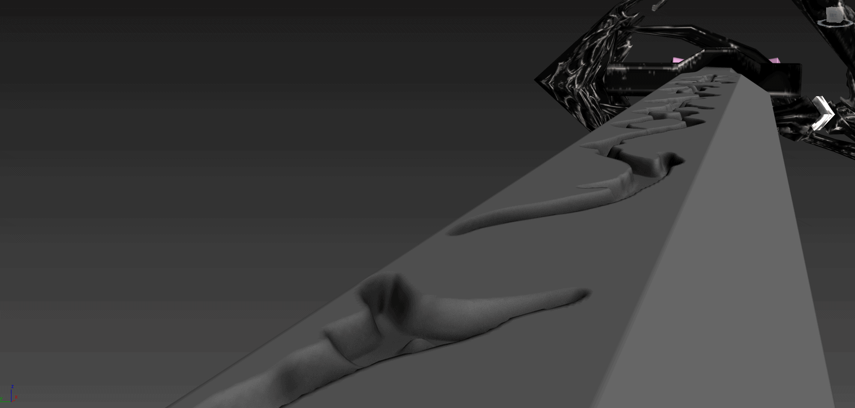
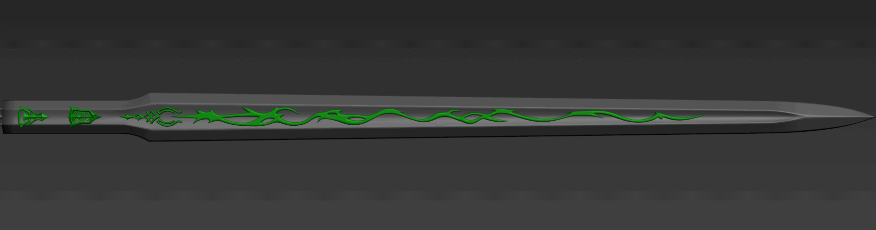
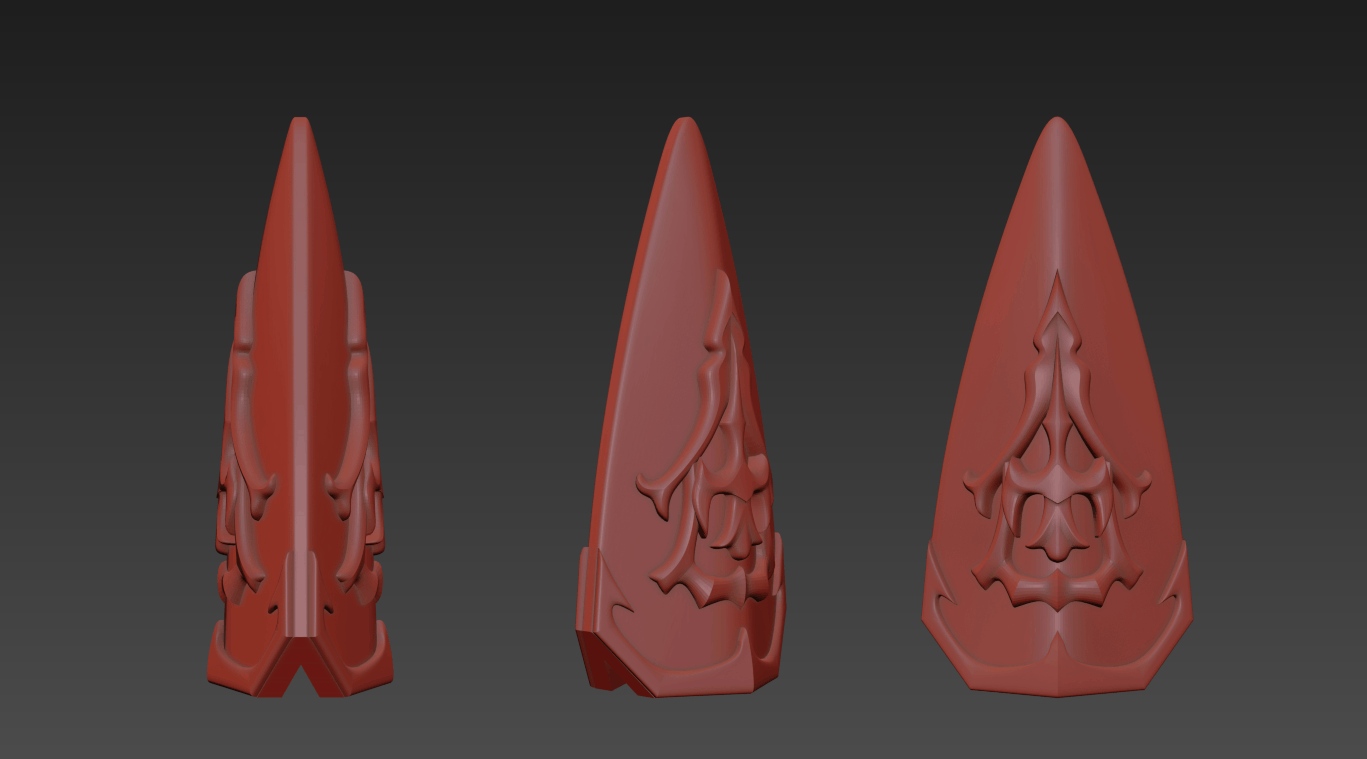
With further review of the references and discussion with the client, we determined that the ‘flat’ of the blade was actually concave, and the runes along its length were likely outward projections, rather than inward carvings. We revised the blade model and created the rune elements as separate objects so that we could reposition and adjust them as necessary.
Definitely a needed improvement. I used the reference material I had available to try and take some educated guesses as to what the emblems on the sides of the blade actually looked like. None of it was particularly clear, so I did my best to apply some artistic interpretation over the normal map texture.
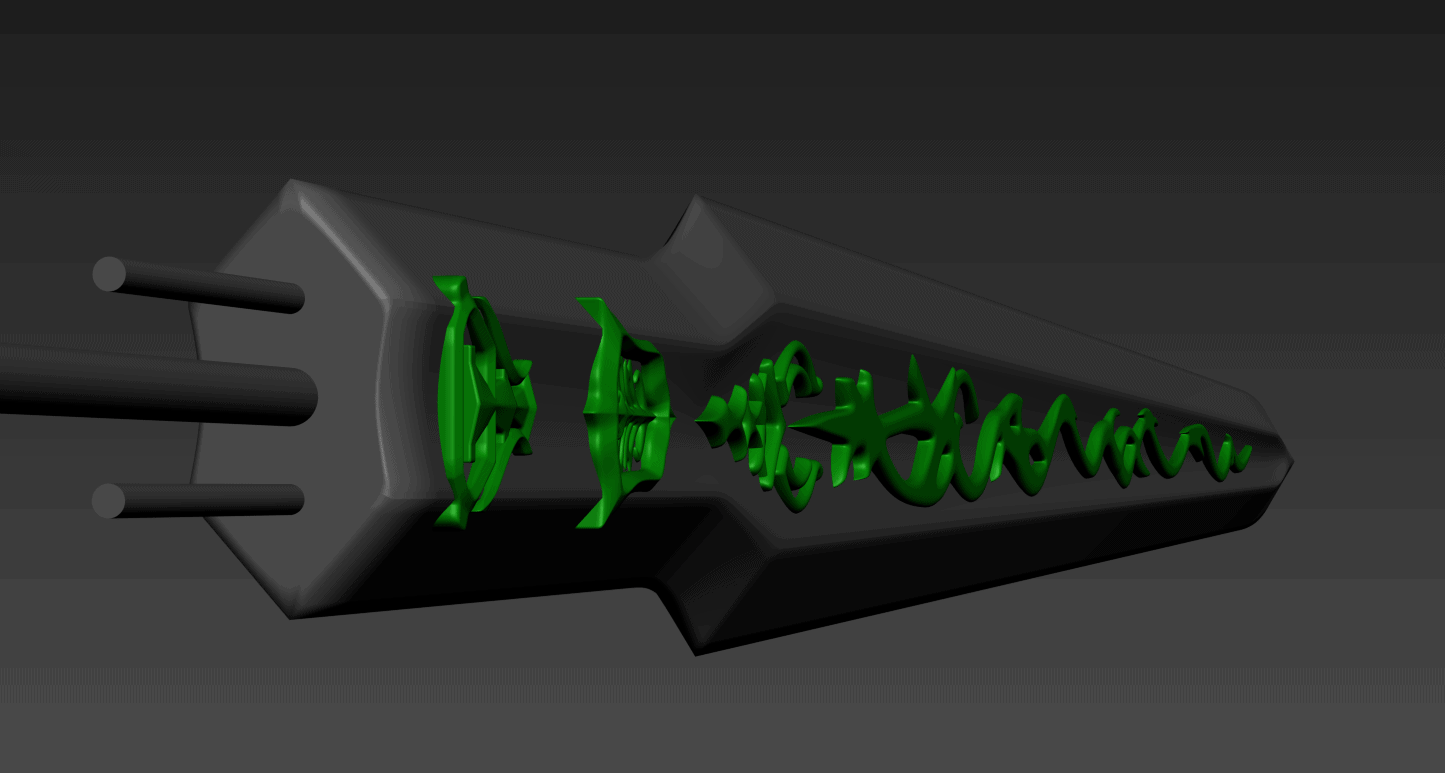
Cylinders were cut out through the length of the blade so the carbon fiber rods could be most of the way through, with enough left to put through the handle.
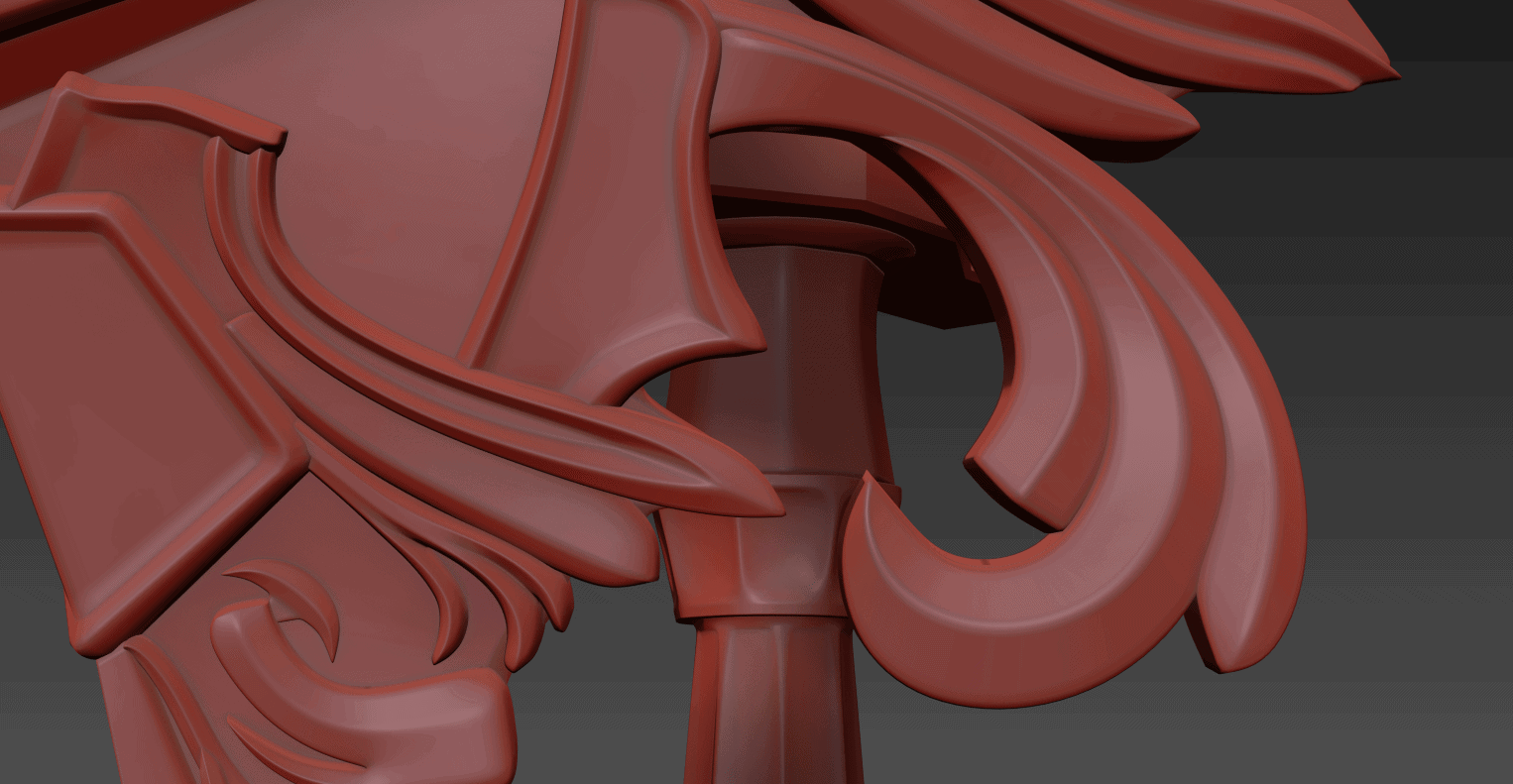
Without a doubt, the ‘shield’ element on the front of the cross-guard ended up being one of the most complicated things I think I’ve ever had to model. It went through multiple revisions while I sorted out a workflow. My early drafts were not pretty, and I have to give kudos to our client for having faith in the process while it took shape.
Much like the quillions and other wrought-iron elements, I started with low-poly, often flat geometry and adjusted from there. A lot of these were done as separate, overlapping elements so that I could individually adjust them per the client’s request if necessary. Given how many times I ended up re-doing some of these parts (on my own initiative, not the client’s!), I’m glad I took this approach.
After a ton of work, I had a copy of the finished sword model that I was happy to present to the client for review and approval.
Then came disaster!
. . .
Okay, not really disaster per se, but literally the same day that I go to show the client the proposed ‘final’ model, I accidentally stumbled onto new reference images. Better reference images. Fantastic reference images, in fact.
This art made a number of additional areas much clearer. Areas that I had been doing some guesswork or creative interpretation of. Areas that now needed attention. God damnit.
REVISIONS
After we discovered this image, the client and I had some discussions about changes he wanted made to certain areas to bring it more in line with the concept art. We also noted some inconsistencies between the design as realized in the game versus what was on this art. For example, the quillions that wrap around the handle and up into the shield both appeared to be on the same side of the sword in the art, whereas the game model has one on either side!
The client’s list of revisions was not at all unreasonable, but the truth is that I can be an obsessive perfectionist. I made my own list of items to revise and took it upon myself to tweak, clean up, or improve a number of areas that were now clarified. I honestly don’t feel like it’s hyperbole to suggest that almost every piece of this was adjusted or re-done one or more times to make sure we got it right.
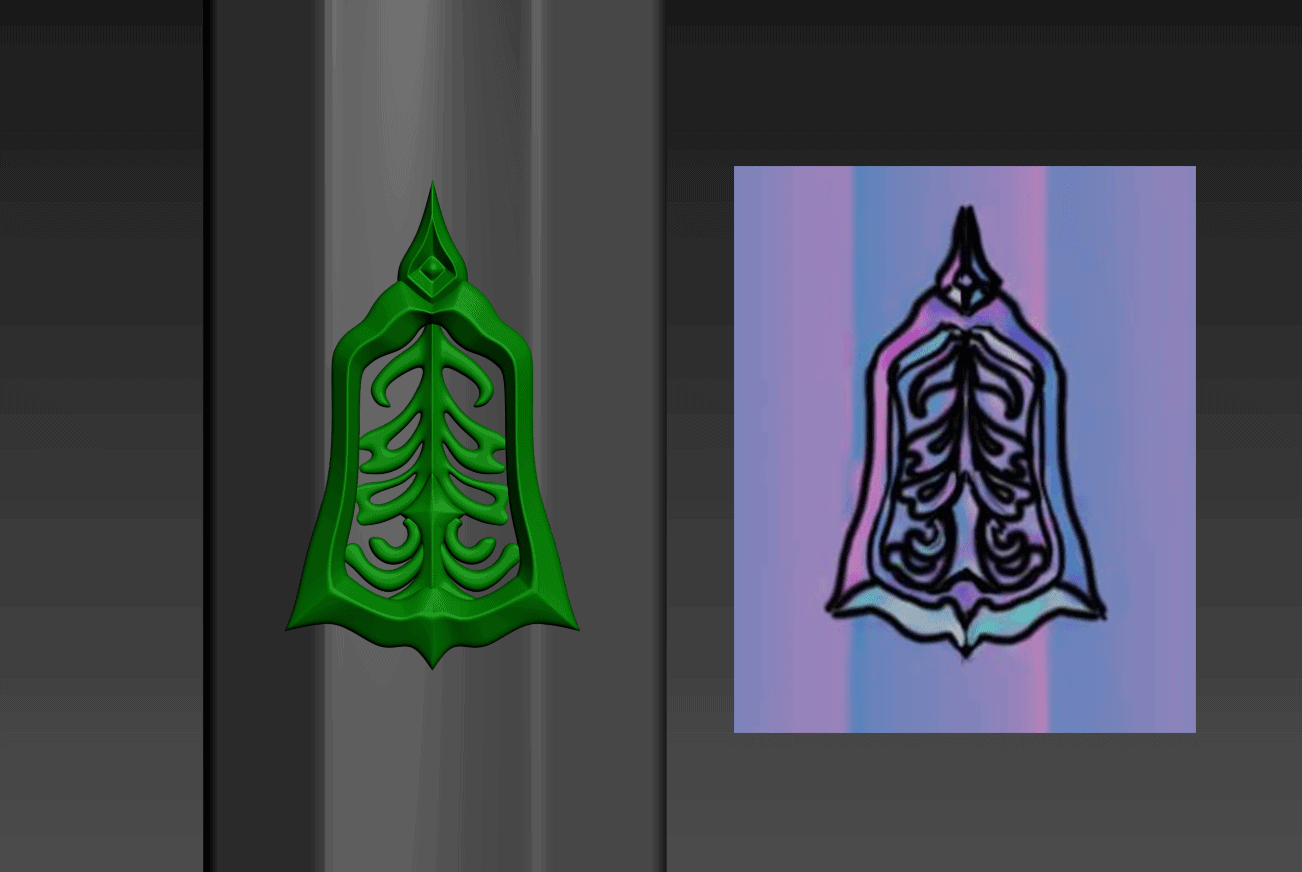
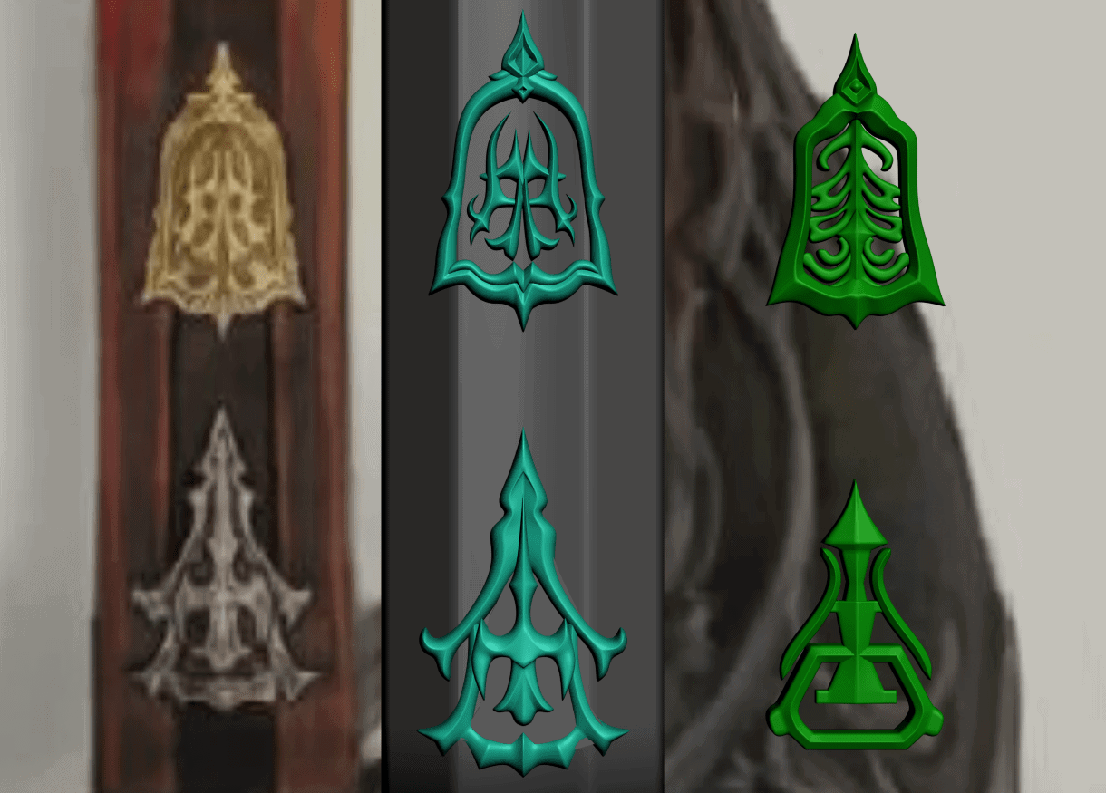
One such area was the crests on the sides of the blade. We actually got the rune detail pretty close to correct, but the rest needed full replacement. Makes what was there look fairly embarassing, to be honest.
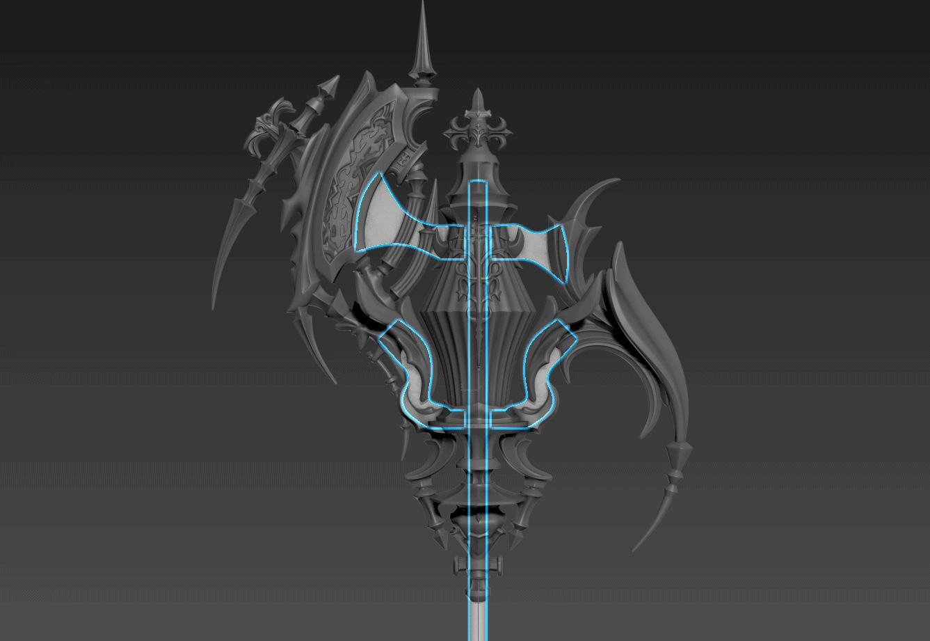
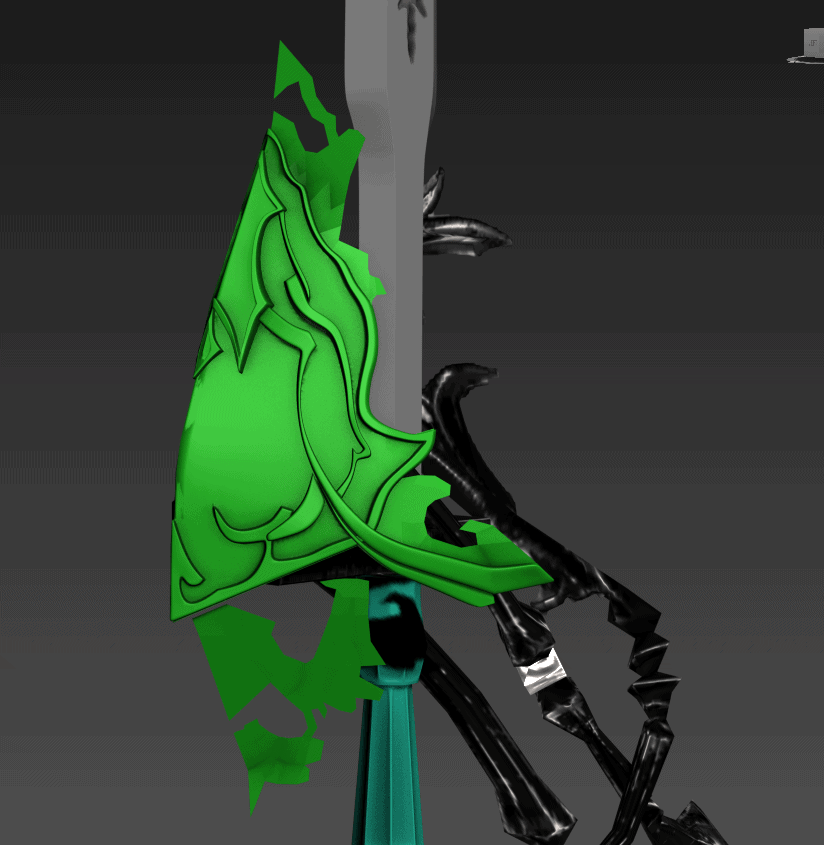
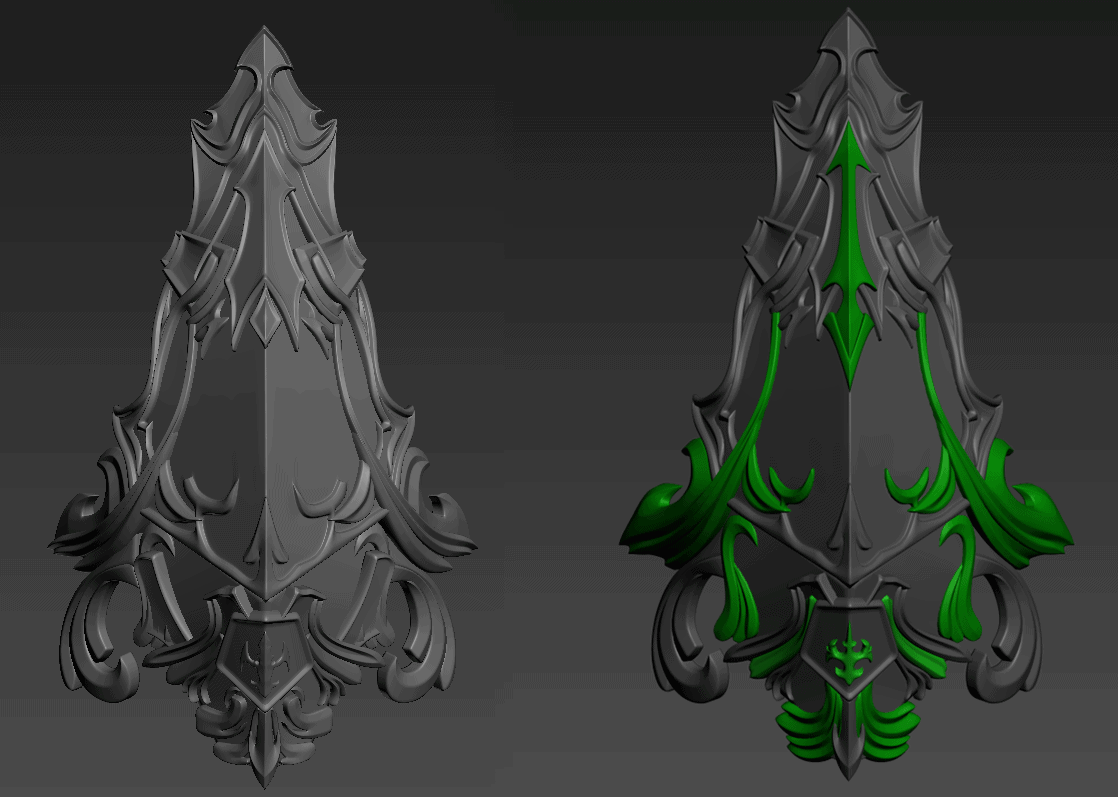
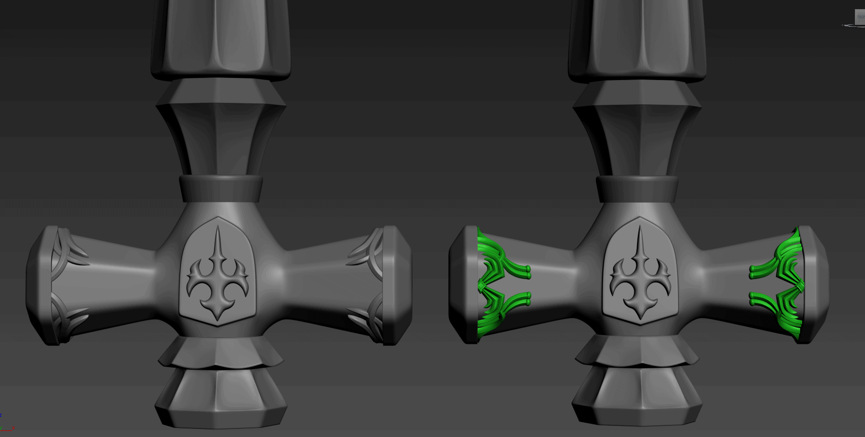
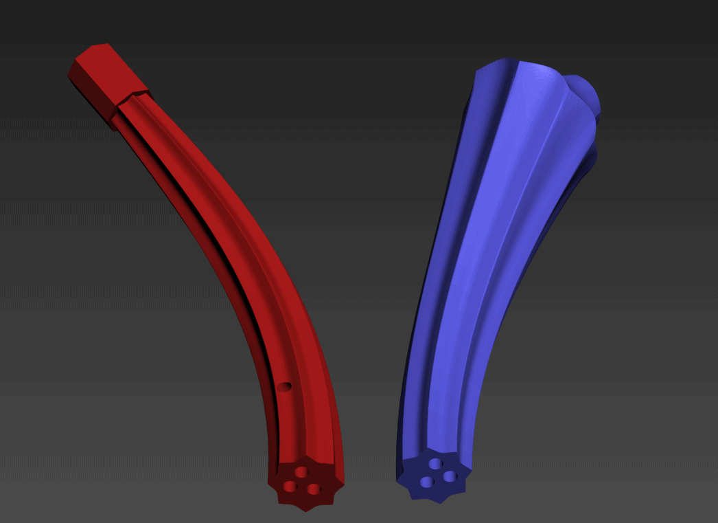
Big revisions were also made to the shield in particular. The ‘wings’ that come off the sides of the shield on the art were much more dynamic and angled in a lot more than what I had designed. The image below shows most (but not all) of the changes that took place, with the original shield on the left and the revised on the right with particular elements highlighted. Other areas were improved or remade, including some of the details along the hilt.
The revisions have taken most of the month of January to get through, but I’m super glad I did them, if only because the thought of knowing what details should have been on this model would have kept me up at night. This gets to be something I can hold up and be proud of for the effort.
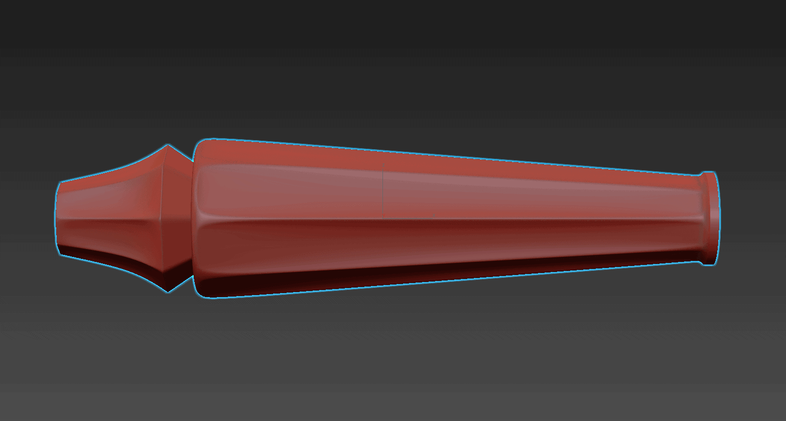
As a last step, I took the liberty of designing a simple ‘cap’ for the tip of the sword. I figured it would help protect the final product during shipping, and the client may want to leave it on there while at a convention for safety reasons.
The final model, pictured above, is a beast. ~4.2 million polygons and a ton of blood, sweat, and tears. If I’m being honest, I vastly underestimated just how much work this model would take design – I’d probably ballpark it at 200 hours of on-and-off work in the evenings, which is an order of magnitude more than I thought it would take initially. On the other hand, I learned a ton during the slog through making the model, so I can’t say I’m unhappy about the work!
SLICING FOR PRINTING
Making the model is a big chunk of the labor for the design, but slicing it to be 3D-printable in a practical way is a job all on its own. I have a Makergear M2, and I adore it. It’s a very robust and reliable machine that is capable of producing high-quality work. However, a printer is only as good as the planning that goes into the files you’re trying to have it produce!
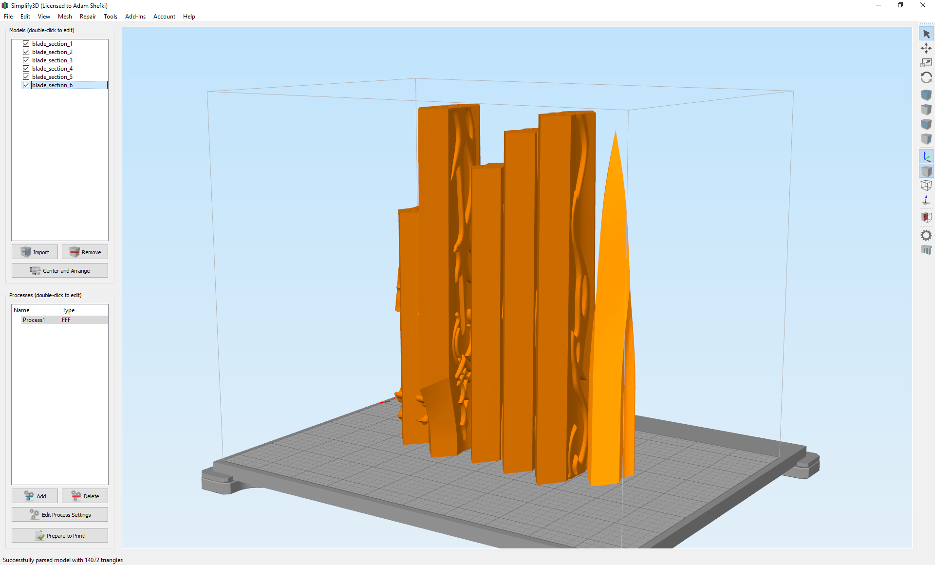
With FDM printers like my M2, you almost always want to minimize overhangs. Areas that float out in space or represent the lower tips of an object can’t be printed without building a support column of plastic beneath them. This is a workable solution, but the supports also tend to leave nasty marks on the surface finish of parts and can waste a ton of filament. Instead, the best approach is one that focuses on creating flat planar surfaces for the machine to build off of the plate with, and minimizes overhangs. In the case of the sword’s blade, for example, you want to cut it into vertical slices that will fit in the machine’s printable area.
I tried to make those cuts in areas with the least detail along the length of the blade, so there would hopefully be less patching or repair work to be done.
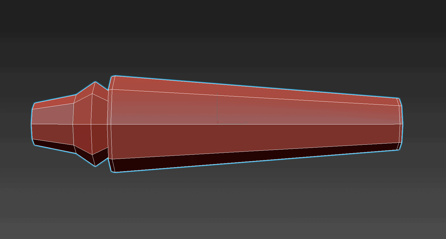
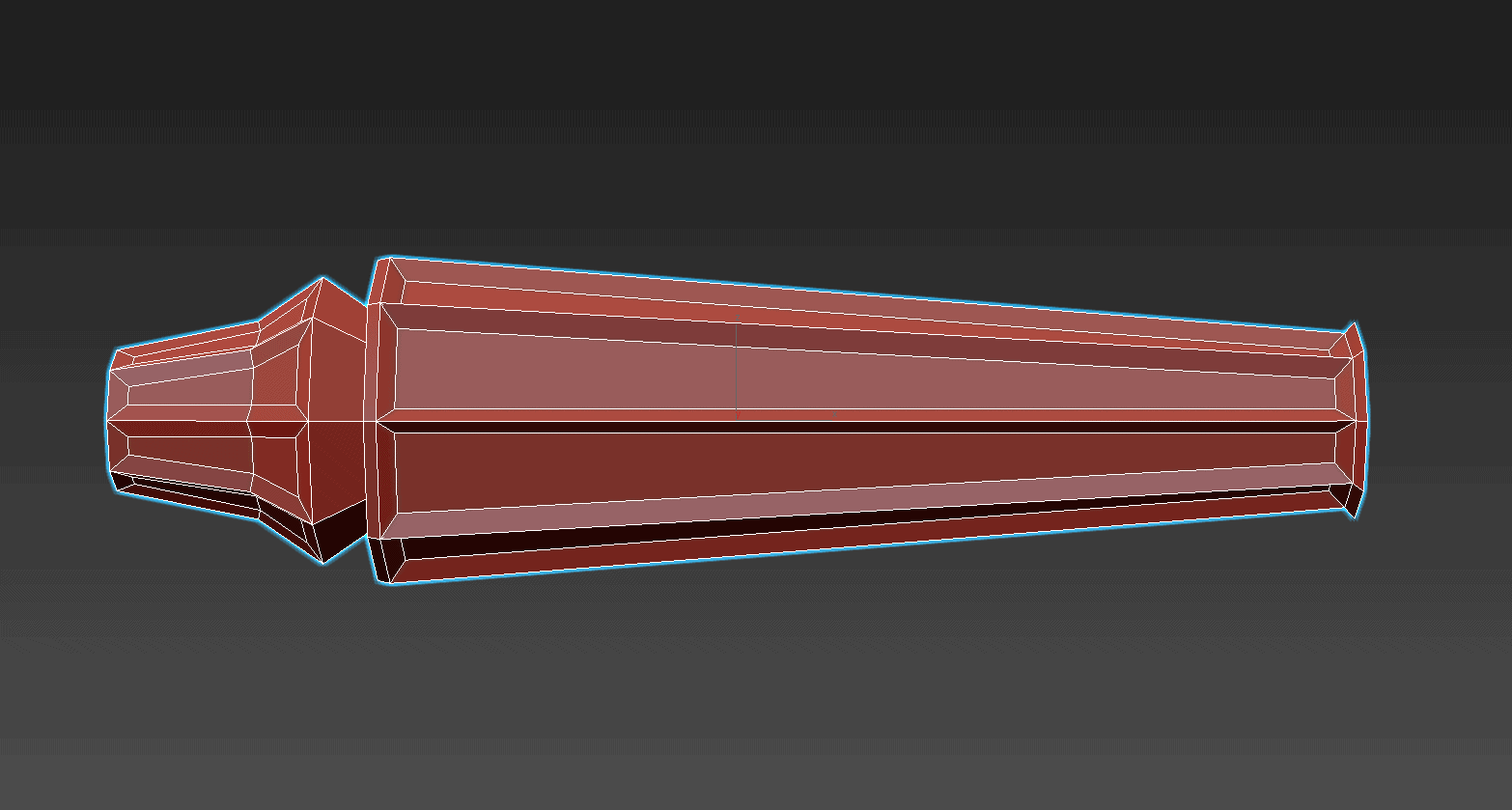
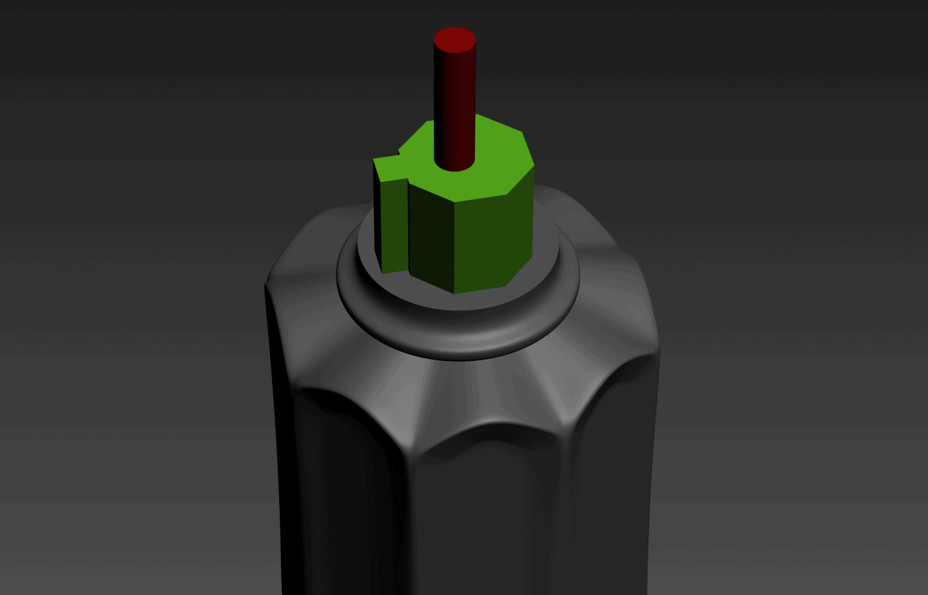
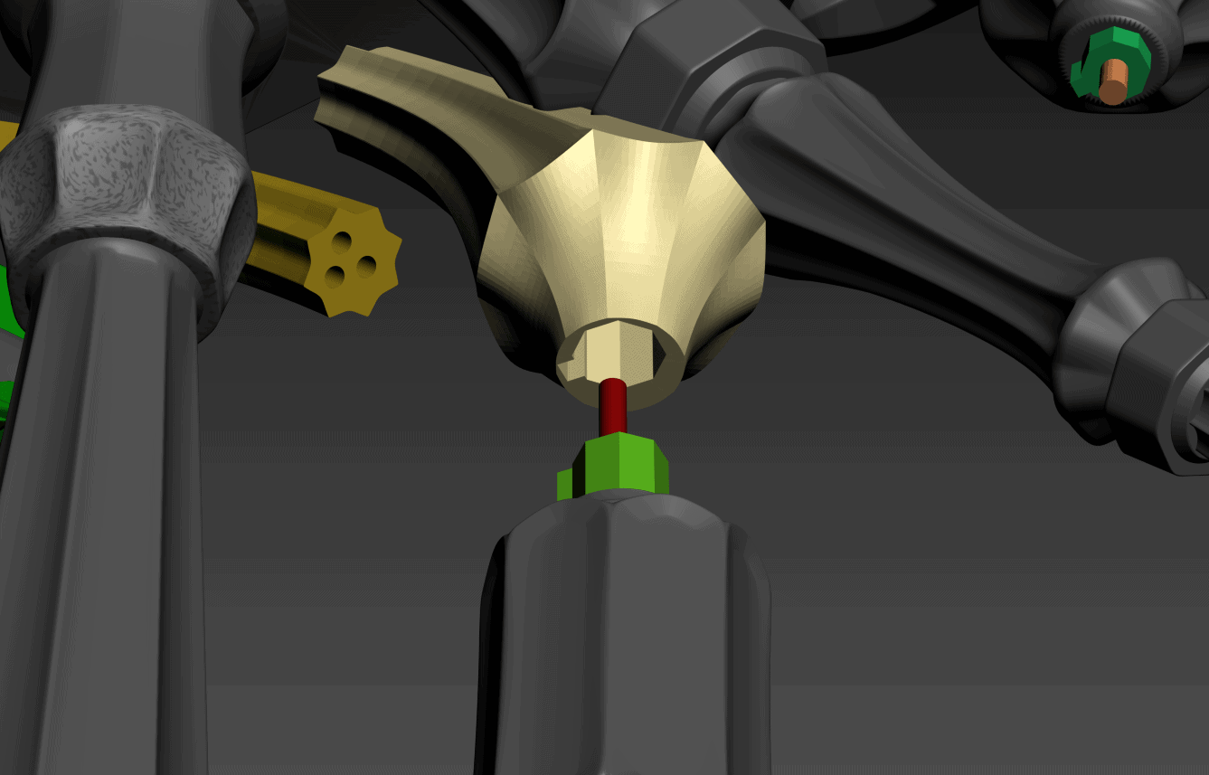
The quillions were slightly more complicated to prep for 3D printing. Each section was divided into a ‘top’ and ‘bottom’ half around the approximate middle of the piece so that I would have a flat surface to build up from on the printer. Another issue was making sure the alignment of every part was correct. The quillions have a very precise configuration, and if you mistakenly assembled one of the joints at the wrong angle or orientation you’d never be able to get it to fit together properly. The spars that run into the back of the shield would never line up! To solve this problem, I used asymmetric alignment keys on the parts that required them.
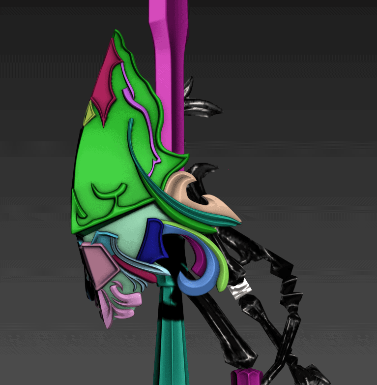
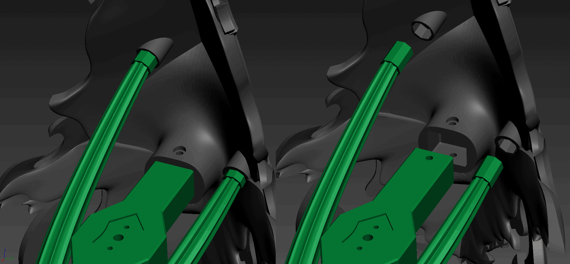
The green portion shows what is added to the component, while the red cylinder is the cutout for a carbon fiber rod that joins two or more parts. These correspond with matching shapes on the opposing part. This cuts out guesswork and makes it difficult, if not impossible, to put parts together at an angle that wasn’t intended. Other areas that might form the ‘bottom’ of a print and therefore needed to be flat were joined with asymmetric hole cut-outs instead.
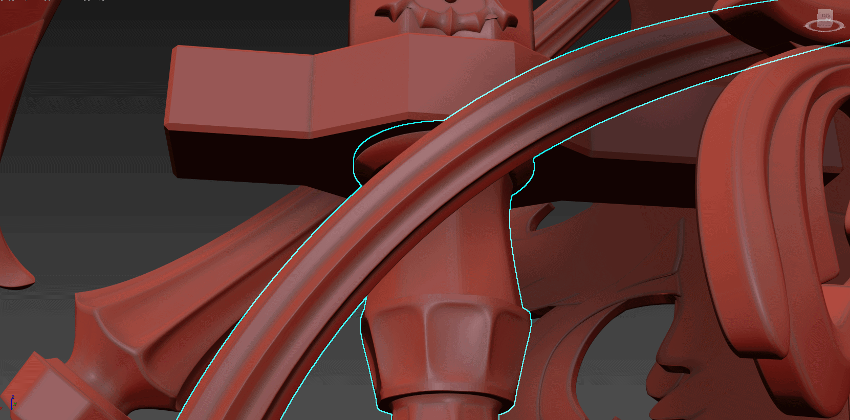
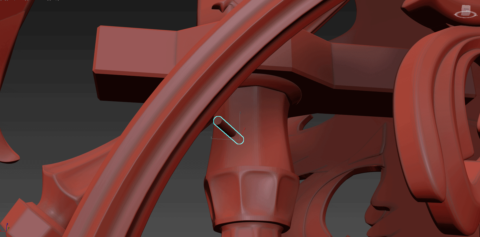
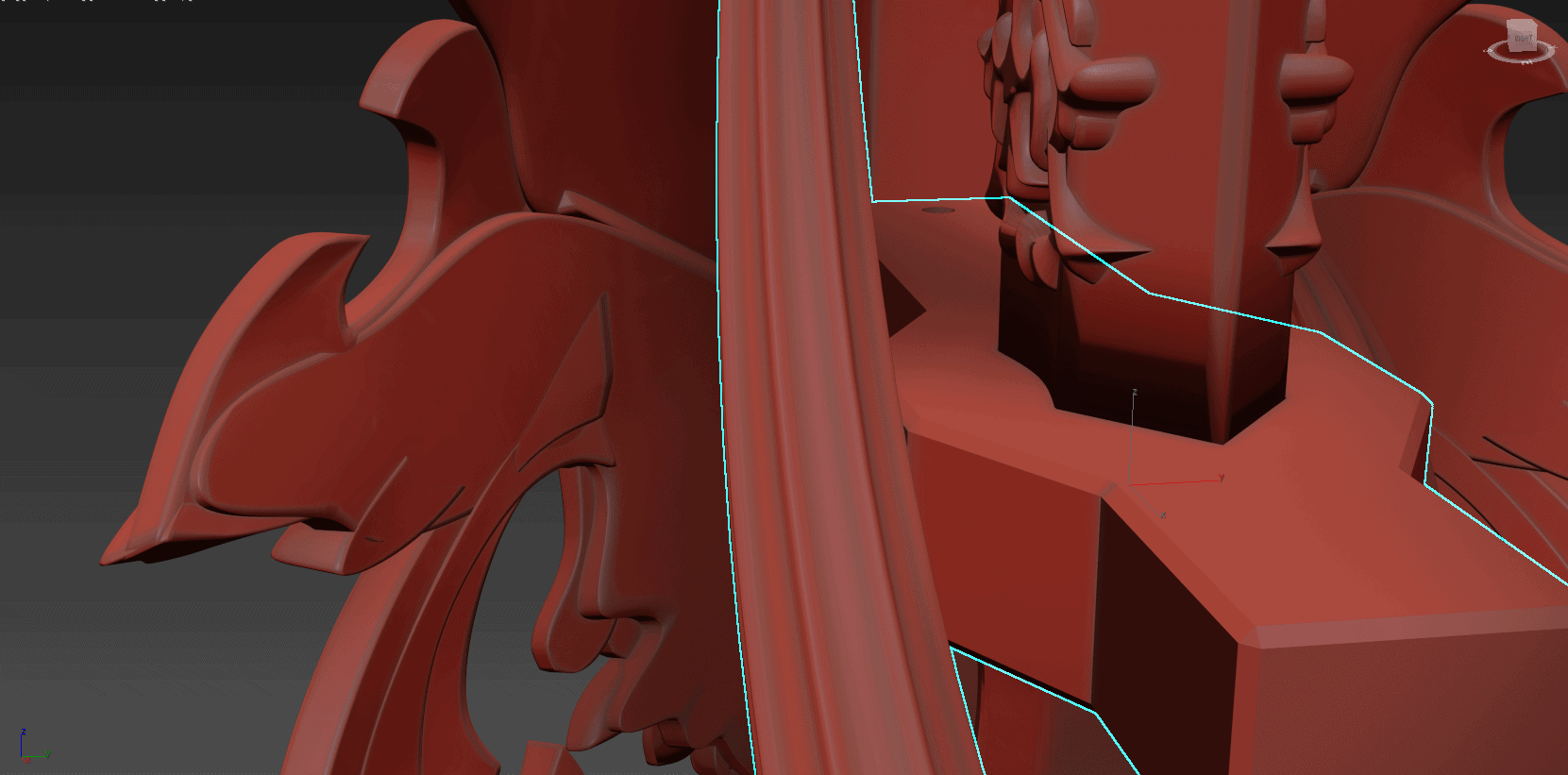
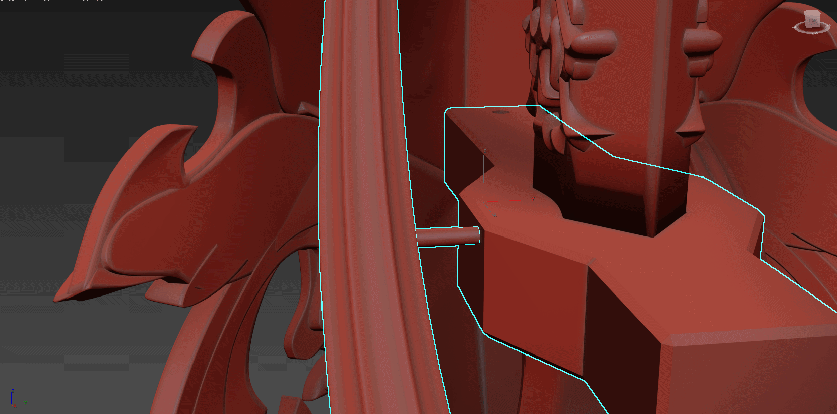
I cut holes in the sides of the two long quillions that connect into the back of the shield in the areas where they pass near the handle so that I could anchor them with hidden carbon fiber rods in those locations, as otherwise the whole wrought-iron design is rather poorly secured.
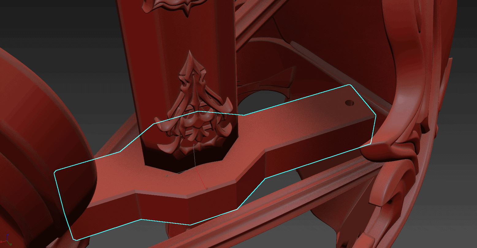
I also added cutouts for rods in any areas I thought might need a bit of extra reinforcement. A vertical hole was added specifically in the cross-guard so I had a mounting point to attach the shield.
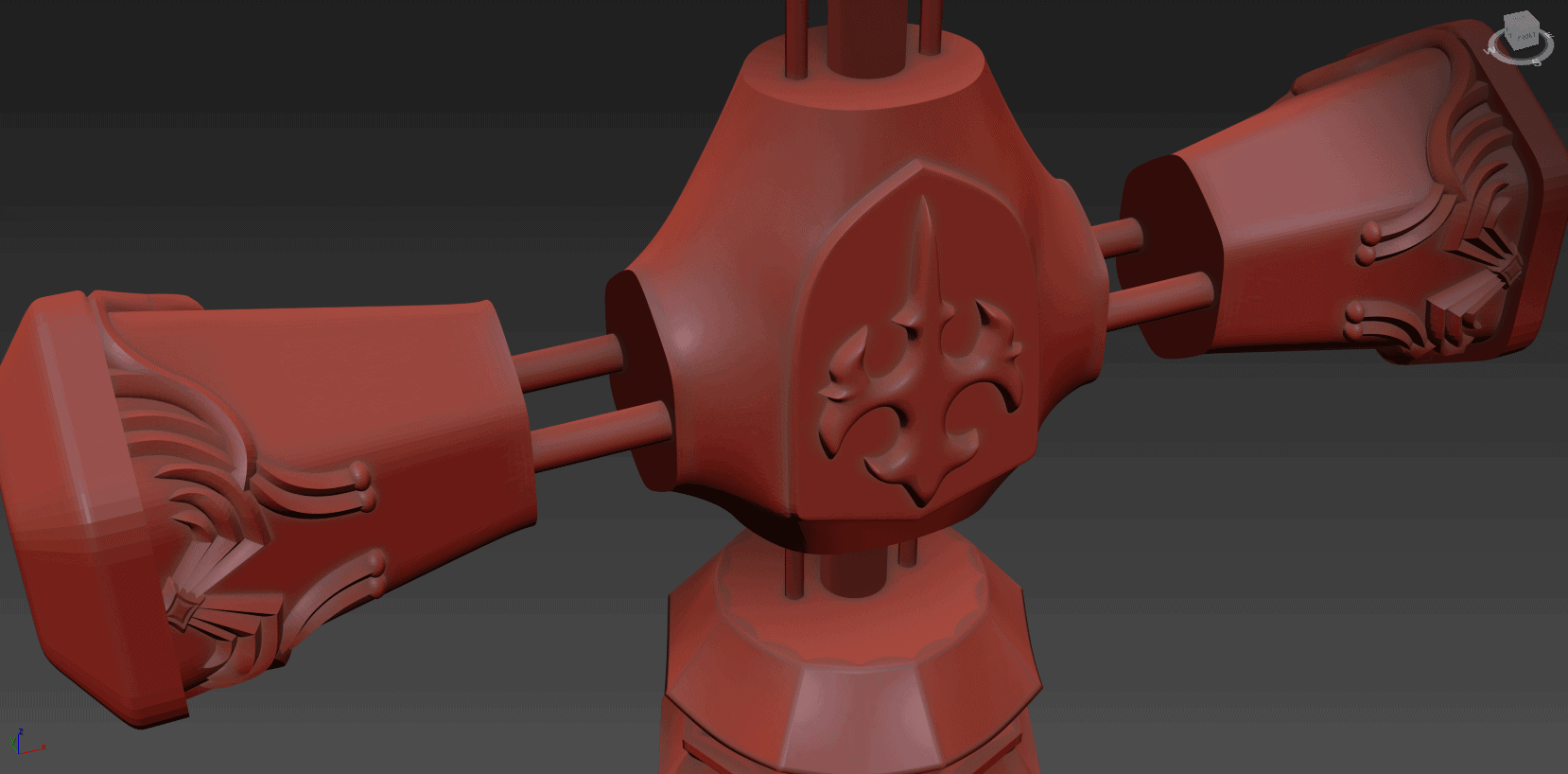
I added some extra geometry to the back of the shield so that I had a way of properly attaching it to the quillions and crossguard. This took the form of some simple plugs for the quillions to match up to, and a square socket in the middle. I anticipated painting the shield and other elements separately, so I wanted to make sure that I could fit these parts together when they had been finished. To that end, I cut a simple hole out vertically through where the shield joins into the crossguard, with the expectation that if I need to, I can simply put an M2 screw through them later.
The back of the shield is one of those areas that will rarely, if ever, be seen, and so I will confess that I was a bit sloppy with how this area looks. My plan is to smooth everything out with bondo or body filler once the shield gets printed.
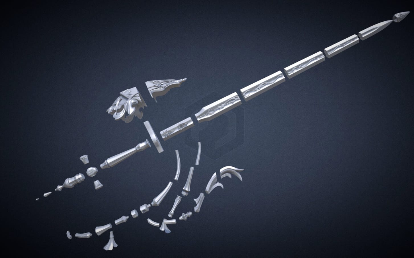
As currently sliced, the sword is printed in 36 parts. You can examine the final parts in exploded view below:
Comments (3)
Hi! Sorry to be a bother, but fan of your content, but I am printing out this sword for a friend of mine (he bought the stls and I have the printer- but that’s how I found your site! So cool) but any way, 2 of your pieces in the stl packet wont even open for me to get to the printer. _ the bottom Cross and Quillion Lower Upper. (sorry to leave a message this way, I don’t see another way to get a hold of you!
Any chance you know what’s up? I have tried to open both of them in multiple programs and I get an error message every time.
Any way, please if you can help let me know! I would really love to have this up and done for my friend so he can get to building!
Shoot me a message and I am happy to give details of friend for you to confirm we have paid for the stls!
Thanks
Hey!
First – you can always reach me at adam@fusedcreations.com if you need to get to me directly.
Second – I’m surprised you’re getting these errors, since I know a bunch of people have bought these files and successfully produced the sword! That said, I’m happy to help you troubleshoot whatever’s going on. I just downloaded the product files and checked and it doesn’t look like I’m having issues opening the files you’ve mentioned, but it might be worth trying to re-download the files from your account page?
In any case, if you shoot me an e-mail I will make sure you get versions of the files you’re having trouble with.
Thank you so much! I just sent an email 🙂 I appreciate the quick response!