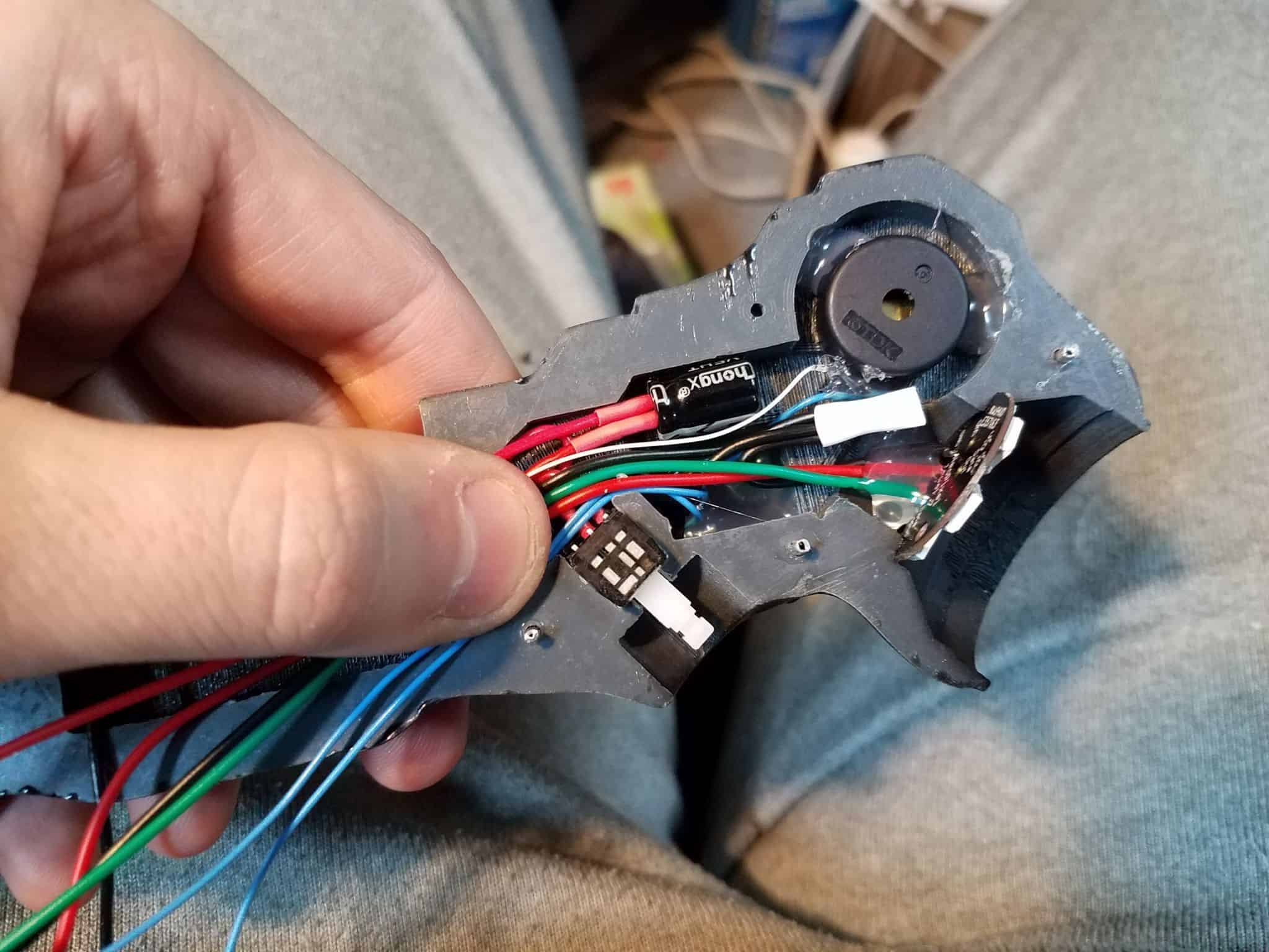
Since I don’t think I’ve done a proper parts breakdown for the Data Knife yet, I’ll post it here. This model was designed around the following parts:
- 12BH510-GR Battery Holder for N-Style Batteries
- A23 12V Batteries
- SPPH410100 Latching Pushbutton Switch
- CPE-220 Piezo Buzzer
- 3mm Blue LEDs x2
- Adafruit Arduino Trinket Microcontroller (5v)
- Adafruit Neopixel Jewel (RGBW – Cool White)
I’ll go on record as saying that the A23 batteries are not ideal. The Neopixel Jewel can draw a lot of current at its peak, and the A23 batteries are basically just a couple of coin cells in a tube. That said, they’re something I had a bunch of lying around, and they fit in the handle without too much hassle. All I’m saying is, buy 10 of them, not just 1, because by the time you’re done testing everything you’ll have gone through 2 or 3.
The switch is also something I just happen to have kicking around. It’s overkill for this, but it’s a push-button toggle with a satisfying amount of travel, so you could do worse.
The Adafruit Trinket is a great little board, but it has some limitations. First, it only has 8kb of programmatic memory to work with, and ~2.5kb of that is taken up by their bootloader (which is excellent, as bootloaders go, by the way!). I trimmed absolutely as much fat as I could from the code below to get it under the Trinket’s default maximum of 5310 bytes, and I was able to get it under that threshhold, but then I discovered that I could use another, bigger Arduino (such as the Uno) to program the trinket and free up all that extra space that the bootloader was taking up. The secret to this is outlined on Adafruit’s site – those particular instructions tell you how to put the bootloader back on in case you screw it up, but the same method can also be used to push code onto the trinket, using the “Arduino as ISP” programmer in the Arduino IDE. Once I found out I could do that, I relaxed a bit, and added a few extra things like the startChime() feature below, which produced a nice little start-up noise. If you’re desperate to fit this on a stock trinket, you can, but you’ll have to comment out some functionality.
This code uses Adafruit’s NeoPixel library, because it is excellent and does what I am not smart enough to do. If you have not installed this library, make sure you do.
#include <Adafruit_NeoPixel.h>
#ifdef __AVR__
//#include <avr/power.h>
#endif

//#include <avr/pgmspace.h>
#define PIN 2 //Used as the Neopixel Data Pin

//The notes below are defined as frequencies here just for reference. You could always change these if you wanted.
#define C7 2093
#define CS7 2217
#define E7 2637
#define FS7 2960
#define G7 3136

Adafruit_NeoPixel strip = Adafruit_NeoPixel(7, PIN, NEO_RGBW + NEO_KHZ800); //setup for using a Neopixel Jewel.
const byte startGreen = 120;
const byte startRed = 255;
const byte startBlue = 0;
const byte startWhite = 5;
const byte endGreen = 0;
const byte endRed = 0;
const byte endBlue = 255;
const byte endWhite = 30;
const float startSpinDelay = 35;
const float endSpinDelay = 20;
const byte totalStep = 175;

int currentStep = 0; //used a simple step variable instead of reading millis() for time to save space.
int currentSpinDelay = startSpinDelay; //This is its own variable because the spin delay ramps up over time.
int currentPixel = 6;
int oppositePixel = 4;
int nextPixel = 1;
volatile uint32_t toggle_count = 0; //used in the sorcery that makes the TrinketTone() function go.

// IMPORTANT: To reduce NeoPixel burnout risk, add 1000 uF capacitor across
// pixel power leads, add 300 - 500 Ohm resistor on first pixel's data input
// and minimize distance between Arduino and first pixel.  Avoid connecting
// on a live circuit...if you must, connect GND first.

void setup() {
  pinMode(0, OUTPUT);
  pinMode(4, OUTPUT); //0 and 4 are output pins for 3mm blue 'data' LEDs on side of handle.
  strip.begin();
  for (int i = 1; i < 7; i++) {
    strip.setPixelColor(i, endGreen, endRed, endBlue, endWhite); //set all but center to initial start color
  }
  strip.show(); // Initialize all pixels to start position
  //strip.setBrightness(128); //ouch, my eyes
  startChime(); //plays the initializing chirp.
}

void loop() {
  if (currentStep == 0) {
    establishStartColor(); //if we're just starting a cycle, fade in to the initial orange from off
  }
  if (currentStep < totalStep) {
      advancePixel(); //move the focal position around the ring to the next LED
    if ((currentStep > 93 && currentStep < 100) || (currentStep > 133 && currentStep < 140)) { //these are random ranges I picked that 'feel' right for the hacking animation to confirm a partial success and chirp.
      TrinketTone(G7, 15);
      strip.setPixelColor(0,0,0,0,80); //turns the middle LED on a low brightness.
    } else {
      TrinketTone(C7, 15);
      strip.setPixelColor(0,0,0,0,0); //Middle LED back off.
    }
    dataLEDs(); //used to simulate 'data processing' on the two side LEDs.
    currentSpinDelay = easeInCubic(currentStep, startSpinDelay, endSpinDelay - startSpinDelay, totalStep); //causes a slow ramp in acceleration of the LED step speed
    delay(currentSpinDelay);
  } else {
    strip.setPixelColor(0, endGreen, endRed, endBlue, 100);
    pulseOuterRing(false, 20, 5);
    pulseOuterRing(true, 20, 5);
    pulseOuterRing(false, 20, 5);
    pulseOuterRing(true, 20, 5);
    delay(2500);
    resetSteps();
  }
}

/*The Arduino's random() function was making my compile size too big.
 * Easiest way to simulate random noise on the LEDs is to use... actual noise!
 * Using analogRead() on pin 3 picks up atmospheric noise in background radiation
 * and electrical signals. It works well enough to do the job nicely and keeps
 * our sketch size tiny.
 */

void dataLEDs() { //I'm positive there's a less clunky way to write this. Screw it.
  if (analogRead(3) % 2 == 0) {
    analogWrite(0, 255 * currentStep / totalStep);
  } else {
    analogWrite(0, 0);
  }
  if (analogRead(3) % 2 == 0) {
    analogWrite(4, 255 * currentStep / totalStep);
  } else {
    analogWrite(4, 0);
  }
  if (currentStep == totalStep) {
    analogWrite(0, 255);
    analogWrite(4, 255);
  }
}
void startChime() { // Just something that sounded decent for a 'switched on' sound effect through my piezo.
  TrinketTone(CS7, 75);
  delay(30);
  TrinketTone(E7, 75);
  delay(30);
  TrinketTone(FS7, 75);
  delay(30);
  TrinketTone(G7, 75);
  delay(150);
  TrinketTone(CS7, 15);
  delay(20);
  TrinketTone(CS7, 15);
  delay(20);
  TrinketTone(CS7, 15);
  delay(20);
  TrinketTone(CS7, 15);
  delay(20);
  TrinketTone(CS7, 15);
  delay(20);
  TrinketTone(CS7, 15);
  delay(20);
}

void establishStartColor() {
  int startColorSteps = 30;
  for (int i = 0; i < startColorSteps; i++) {
    for (int z = 1; z < 7; z++) {
      strip.setPixelColor(z, easeInOutQuint(i, 0, startGreen, startColorSteps), easeInOutQuint(i, 0, startRed, startColorSteps), easeInOutQuint(i, 0, startBlue, startColorSteps), easeInOutQuint(i, 0, startWhite, startColorSteps));
    }
    strip.show();
    delay(15);
    analogWrite(0, 255 - 255 * i / startColorSteps);
    analogWrite(4, 255 - 255 * i / startColorSteps);
  }
}

void resetSteps() { //function to make the knife start the whole sequence over.
  currentStep = 0;
  strip.setPixelColor(0, 0, 0, 0, 0);
  strip.show();
}

void advancePixel() { //lol I have no idea how to do this cleaner but it works
  if (currentPixel == 6) {
    currentPixel = 1;
  } else {
    currentPixel++;
  }
  if (nextPixel == 6) {
    nextPixel = 1;
  } else {
    nextPixel++;
  }
  if(oppositePixel==6){
    oppositePixel = 1;
  } else {
    oppositePixel++;
  }
  strip.setPixelColor(currentPixel, easeInOutQuint(currentStep, startGreen, endGreen - startGreen, totalStep), easeInOutQuint(currentStep, startRed, endRed - startRed, totalStep), easeInOutQuint(currentStep, startBlue, endBlue - startBlue, totalStep), easeInOutQuint(currentStep, startWhite, endWhite - startWhite, totalStep));
  strip.setPixelColor(nextPixel, 0, 0, 0, 0);
  strip.setPixelColor(oppositePixel,0,0,0,0);
  strip.show();
  currentStep++;
}

/*The easing functions below are used to animate the LEDs a little smoother.
 *easeInCubic is mostly for single direction fades and for the ramp in LED spin speed.
 *easeInOutQuint is used to transition between the initial orange color of the hacking animation
 *through to the final blue color. A linear transition spent a lot of time going through white
 *hues and didn't look right. This easing basically zips quickly through the middle of that gradient
 *and slowly through either end. Demonstrations at http://gizma.com/easing/
 */

float easeInCubic (float timeInSteps, float beginValue, float changeValue, float durationValue) {
  return changeValue * (timeInSteps /= durationValue) * timeInSteps * timeInSteps + beginValue;
}

float easeInOutQuint (float t, float b, float c, float d) {
  t /= d / 2;
  if (t < 1) {
    return c / 2 * t * t * t * t * t + b;
  }
  t -= 2;
  return c / 2 * (t * t * t * t * t + 2) + b;
};

void pulseOuterRing(bool goUp, int pulseSteps, int pulseDelay) { // animation used to confirm a successful hacking.
  byte mult; //this byte is basically just used to track which direction the pulse is going - fading in, or fading out.
  TrinketTone(G7, 75);
  for (int i = 0; i < pulseSteps; i++) { for (int z = 6; z > 0; z--) {
      if (!goUp) {
        mult = i;
      } else {
        mult = 20 - i;
      }
      strip.setPixelColor(z, endGreen - (endGreen / pulseSteps * mult), endRed - (endRed / pulseSteps * mult), endBlue - (endBlue / pulseSteps * mult), endWhite - (endWhite / pulseSteps * mult));
    }
    strip.show();
    delay(pulseDelay);
  }
}

/* The Trinket and its ATTiny85 processor cannot, by default, use the arduino tone() library.
 * This is a huge pain in the ass. However, Bruce E. Hall of www.w8bh.net is a brilliant dude
 * and has made my life immeasurably easier by providing a TrinketTone() function and some
 * basic ISR timer stuff that runs at some higher hardware level than I genuinely understand.
 * Needless to say, it works, it's small enough to fit on the trinket, and I am grateful as hell.
 * http://w8bh.net/avr/TrinketTone.pdf and http://w8bh.net/avr/TrinketTimers.pdf are great resources.
 */

void TrinketTone(uint16_t frequency, uint32_t duration) {
  // scan through prescalars to find the best fit
  uint32_t ocr = F_CPU / frequency / 2;
  uint8_t prescalarBits = 1;
  while (ocr > 255)
  {
    prescalarBits++;
    ocr /= 2;
  }
  // CTC mode; toggle OC1A pin; set prescalar
  TCCR1 = 0x90 | prescalarBits;

  // Calculate note duration in terms of toggle count
  // Duration will be tracked by timer1 ISR
  toggle_count = frequency * duration / 500;
  OCR1C = ocr - 1; // Set the OCR
  bitWrite(TIMSK, OCIE1A, 1); // enable interrupt
}

ISR(TIMER1_COMPA_vect) {
  if (toggle_count != 0) { // done yet?
    pinMode(1, OUTPUT); //if it's already in Output mode, nothing happens, tone continues.
    toggle_count--; // no, keep counting
  } else { // yes,
    pinMode(1, INPUT); //switching the pin to Input immediately stops the tone signal.
  }
}


Comments (9)
following your tutorial, when i go to upload the code to the trinket, i get an error about the pins_arduino.h no such file or directory, and I am at a complete loss at how to go about fixing it. thank you for your time.
I actually had the exact same error at one point, if I recall. I’m assuming you’re using the standard Arduino IDE?
I was having issues when I was trying to program the Arduino from a different computer than the one I normally use. I am pretty sure I recall the issue being at least in part due to some missing files under the /cores/ or /variants/ folders in C:\Program Files (x86)\Arduino\hardware\arduino\avr
Don’t hold me to this 100%, but I want to say one of these things fixed the issues:
Make sure you have a “tiny8” folder under C:\Program Files (x86)\Arduino\hardware\arduino\avr\variants (or wherever comparably installed on your machine). I’m including a link to a copy of these in a .rar file for you to try if you don’t have the folder in that location:
https://www.fusedcreations.com/wp-content/uploads/2020/10/arduino_repair.rar
I think I might have had it in there from an older version of the Arduino IDE, when you had to install all this crap manually, and that might be part of why it works.
In the event the above step doesn’t fix it, you’ve got some kind of mismatch in the Arduino.h file. Try putting the “cores” folder in the .rar volume above into C:\Program Files (x86)\Arduino\hardware\arduino\avr and see if that fixes it.
Let me know which (if either) of the things above resolves it. I know one or the other of these was what fixed it on my other PC, but I can’t honestly remember which. If neither works, I may be out of ideas until I have more information.
So putting the tiny folder into the variants folder has been a success and the board is producing the sound through the piezo when test connected to the ground and pin 1 on the trinket. again thank your for your time.
Awesome! Glad to hear it. Let me know if you need any other help!
Hi, thank you so much for the tutorial and great work. Unfortunatelly something did not work properly in my build. The LEDs have different colors while the sequence and at the end 4 of the outer 6 LEDs are green, one is red and one is blue. The center LED ist also blue. Don´t know whats going on there. Did you?
Hi Nils,
Unfortunately, what you’re describing could have a lot of causes.
– Are the other functions of the sketch working correctly? Meaning, is the audio playing through the piezo buzzer, and are the blue LEDs flickering as they’re supposed to? If not, something’s probably wrong with your sketch upload, and you might need to check the clock speed you’re using when you upload the sketch.
– Are you using a fully-charged power source? Neopixel behavior can get weird if not provided with enough voltage./
– Are you using RGB Neopixel rings, or RGBW ones? If you’re using just regular RGB ones instead of RGBW, the signal being sent to the neopixel ring is not going to be understood by the LEDs.
– Test your wiring – if you upload a simple strandtest sketch to the arduino while it’s hooked up to the neopixel rings, are they behaving as expected? If not, something might be wrong in how you have the device wired together.
If you need further help, you can e-mail me at adam@fusedcreations.com with pictures of your setup and I’ll try to help you diagnose.
Hi Adam,
thank you so much for your help and your quick response. I checked everthing you wrote and the Neopixel ring that I used is an RGB one, not the RGBW version… I am so sorry for wasting your time. I am going to buy the RGBW one and will test it again. Everything else works fine in the sketch 🙂
Hey Nils,
Glad you worked that out! It should actually be possible to tweak the sketch such that it’d work for the RGB ring if you wanted – you’d need to change the Adafruit_Neopixel strip declaration at the top to NEO_RGB and strip out any references to the white values in the functions. For instance, the strip.setPixelColor function can accept strip.setPixelColor(LED_INDEX, RED, GREEN, BLUE, WHITE), but you could also just change it to be strip.setPixelColor(LED_INDEX, RED, GREEN, BLUE), since the function permits that. Where a function might go:
strip.setPixelColor(0,0,0,0,80); //turns the middle LED on a low brightness.
… you could substitute, instead:
strip.setPixelColor(0, 80, 80, 80);
The mixing of equal values of Red, Blue, and Green approximate white well enough, though it would be dimmer than if you had used an RGBW ring.
Anyway, glad you’ve got a way forward with it! Let me know how it goes.
Hi Adam,
I changed the Neopixel ring to the RGBW version and everything works fine now. Thank you so much for your great support!