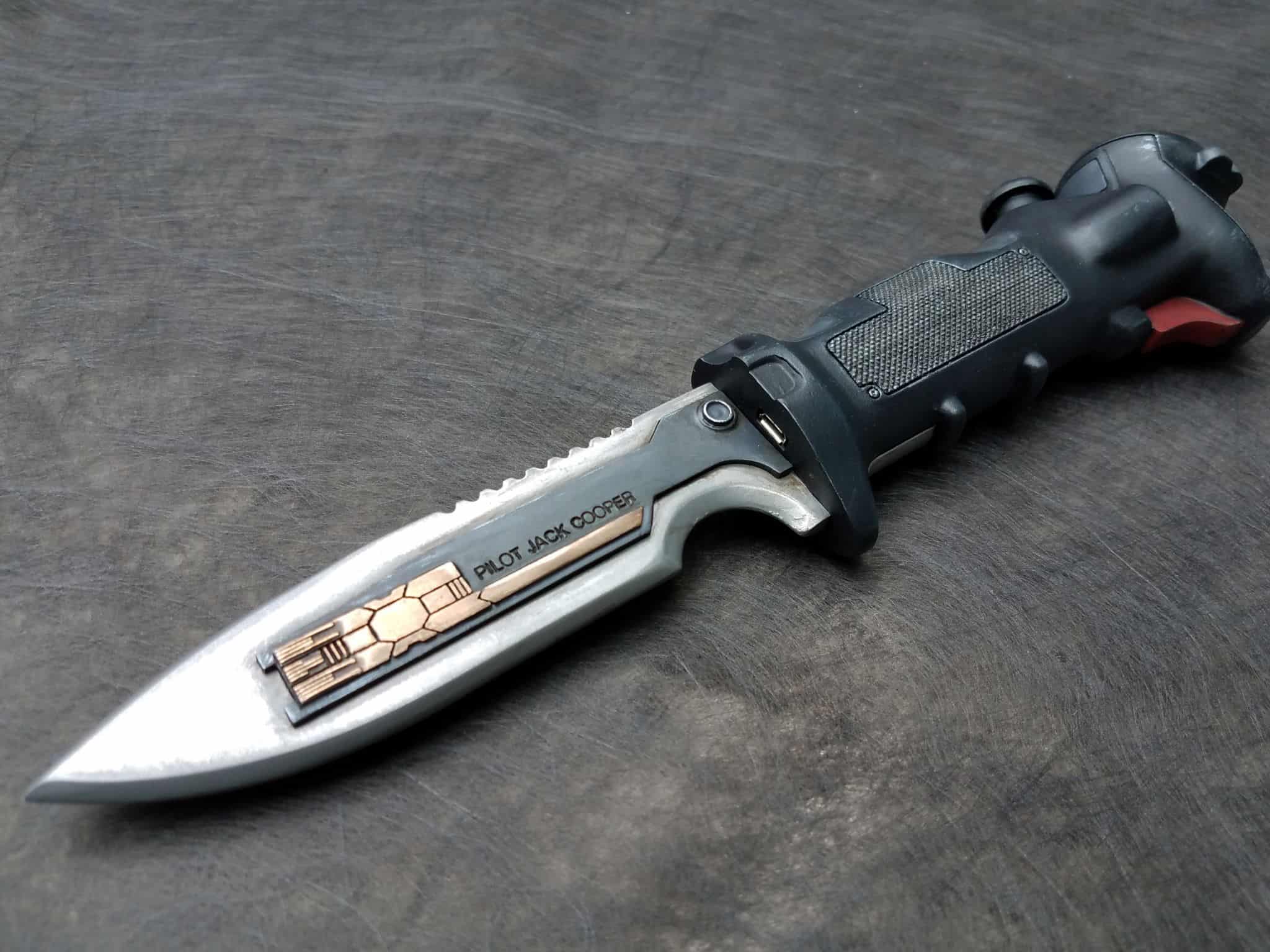
I’ve had a few messages requesting a better explanation of how the data knife goes together, so I sat down with a spare print of the handle and photographed the process in the hopes that it might help folks trying to follow along. Before that, though, lets talk about programming the 5V Adafruit Trinket. I am assuming some level of familiarity with arduino and the Arduino IDE here, because I can’t teach all of that in a single forums post – this is more an explanation of the particular methods required to get the setup I have.
The Trinket comes with a bootloader, which is a clever bit of software that lets you upload files (sketches) to be run by the microprocessor. However, the trinket only has 8kb of memory total, and the bootloader takes up about 2.5kb of that, which only leaves you with ~5.5kb to work with. The code I came up with to run the knife is just a liiiiiitttle bit bigger than that. It’s not the end of the world, though! We’re going to remove the bootloader. This is actually a good thing. The bootloader delays the arduino when you first turn the device on because it’s waiting to see if you’re going to upload code for a few seconds. Removing the bootloader means that the knife goes right into its animation when you turn it on, rather than sitting idle for a few seconds. It also frees up the full 8kb of memory on the trinket to work with. I was able to figure out how to do this thanks to Adafruit’s tutorial on repairing the bootloader – you’re basically doing the same process, but rather than putting the bootloader on, putting the knife code.
To program it without the bootloader, you’re going to need another Arduino. I’d strongly recommend grabbing an Arduino Uno (R3), as it’s a good thing to have to test code out on anyway. It also doubles as a programmer in situations like this – acting as an intermediate interpreter and control unit to ‘teach’ the trinket what to do. The Arduino IDE has a sketch on it called “ArduinoISP” under examples. Plug your Arduino Uno in, hook it up via USB to your computer, set the Board to Arduino Uno and set the Programmer to AVRISP mkII. Hit upload, and let the Uno capture the code.
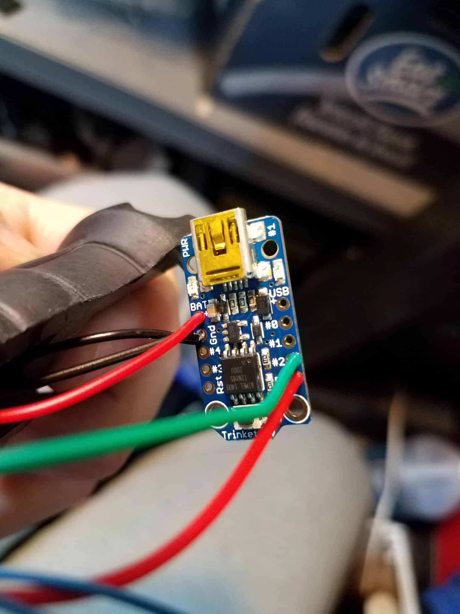
Once that’s done, you need to start setting up the connections between the Uno and the 5v Trinket. Connect as follows:
- Trinket VBAT+ pin to Arduino 5V (or just power it via a battery or USB cable)
- Trinket GND pin to Arduino GND
- Trinket RST to Arduino #10
- Trinket #0 pin to Arduino #11
- Trinket #1 pin to Arduino #12
- Trinket #2 pin to Arduino #13
Now, you’re going to have to teach your Arduino IDE what the hell you’re doing, because if you try to upload it using the default Trinket profiles it will object on the basis that it knows a default trinket, with bootloader, only has about 5.5kb of usable memory space, rather than the full 8kb, and the sketch is bigger than that. To fix this, you need to go to where you have your Arduino IDE installed and find the ‘boards.txt’ file. (C:\Program Files (x86)\Arduino\hardware\arduino\avr\boards.txt, in my case). Add this profile to the file:
# Trinket 5V Configuration
trinket5.name=5v Trinket 16MHz No Bootloader
trinket5.bootloader.low_fuses=0xF1
trinket5.bootloader.high_fuses=0xD5
trinket5.bootloader.extended_fuses=0xFE
#trinket5.bootloader.tool=arduino:avrdude
trinket5.build.mcu=attiny85
trinket5.build.f_cpu=16000000L
trinket5.build.core=arduino:arduino
trinket5.build.variant=tiny8
trinket5.build.board=AVR_TRINKET5
trinket5.upload.tool=arduino:avrdude
trinket5.upload.maximum_size=8192
Now, restart your arduino IDE, and you should see the correct settings listed. Pick the “5v Trinket 16Mhz No Bootloader” option under the boards menu, set your programmer to “Arduino as ISP”. Click upload, and your IDE will push the code through you Arduino Uno and onto the Trinket. You should see the red light on the trinket flashing in time with the data transmission LED on the Uno. Easiest way to test the trinket afterwards is to power it and hook the piezo buzzer up between pin 1 and ground with my knife code – if it’s making the correct noises, you’ve done it right.
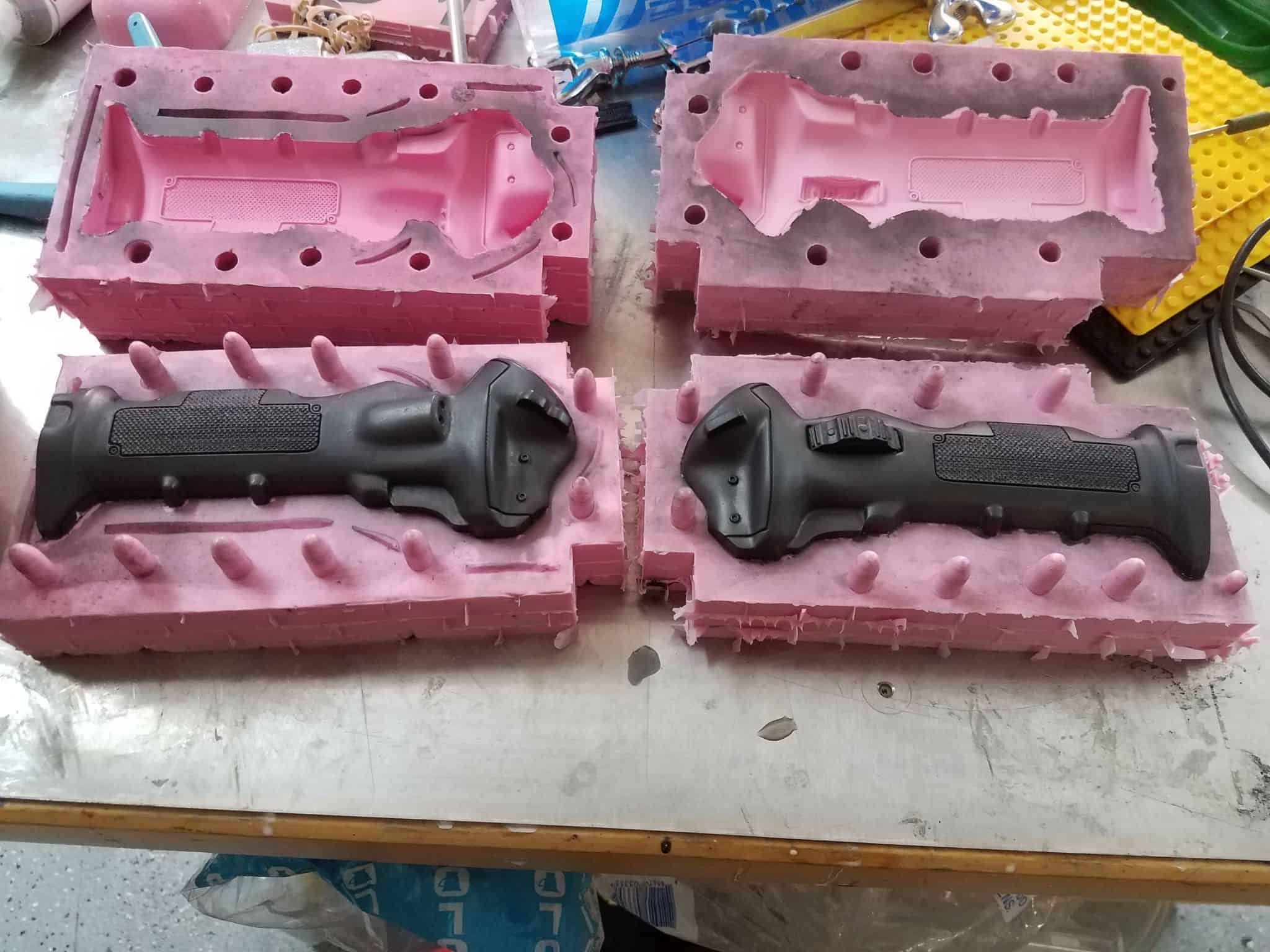
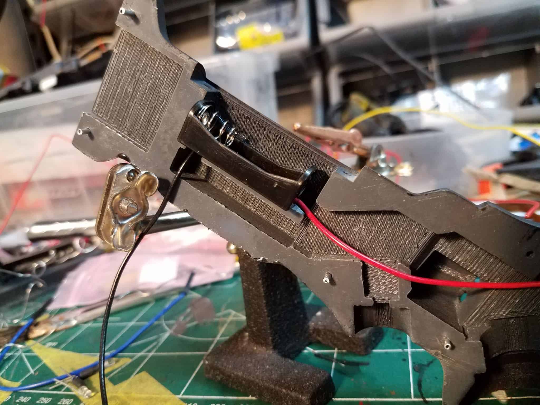
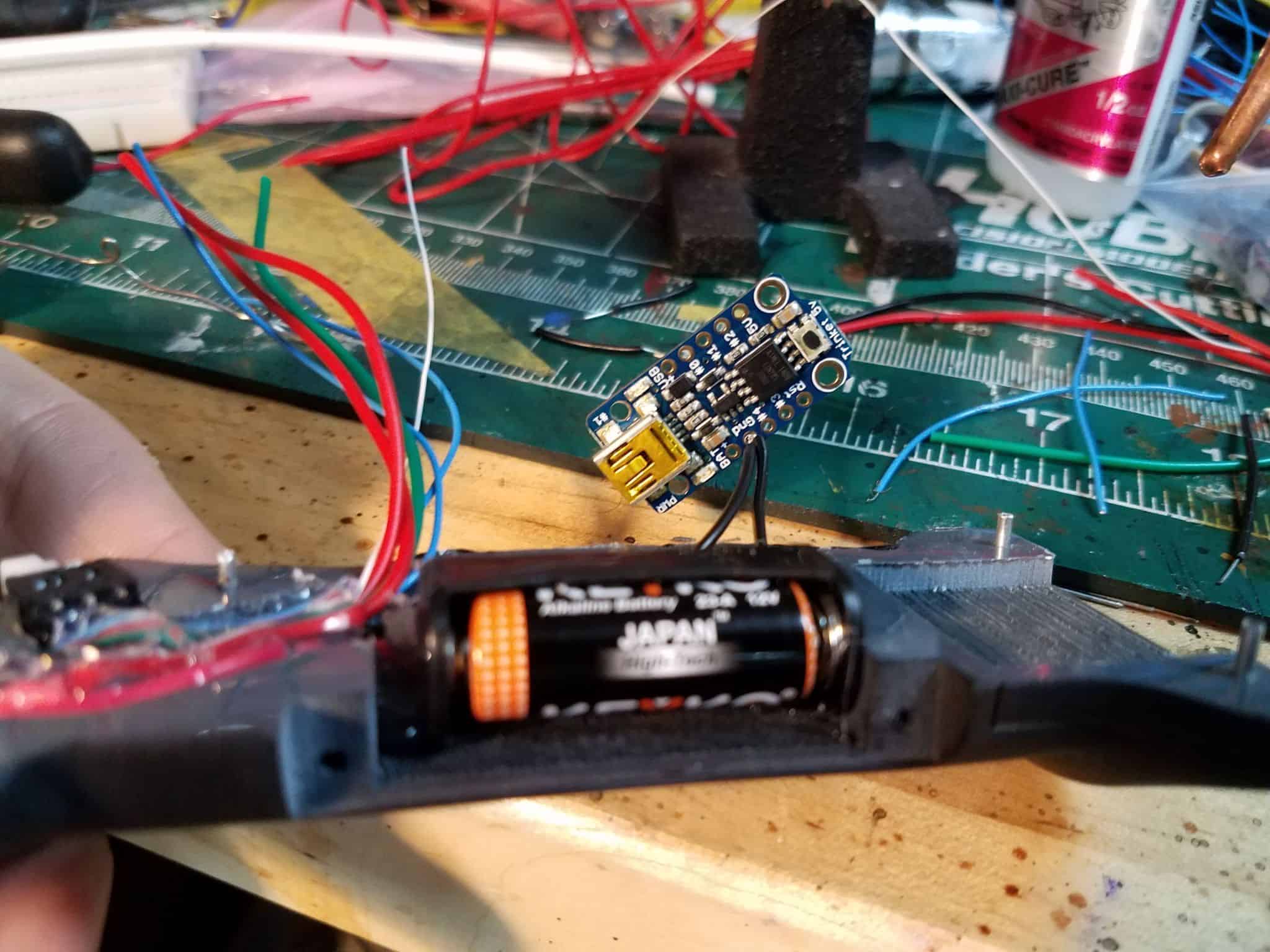
Now, let’s talk about actual assembly. To start with, take the battery enclosure and glue it into place. I use cyanoacrylate superglue to get the initial contact between parts, and followed it up with hot glue to fill a bit of the extra space.
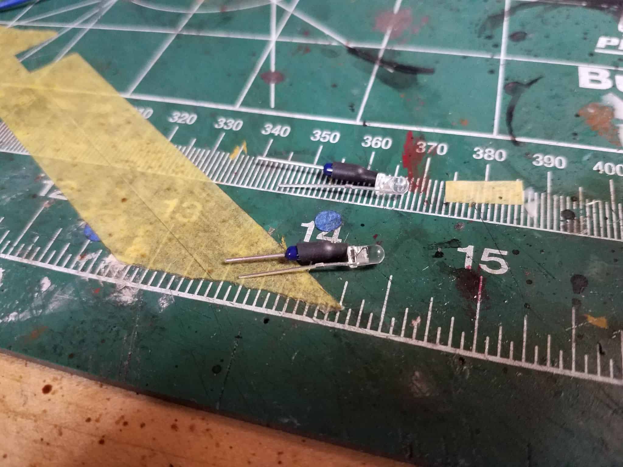
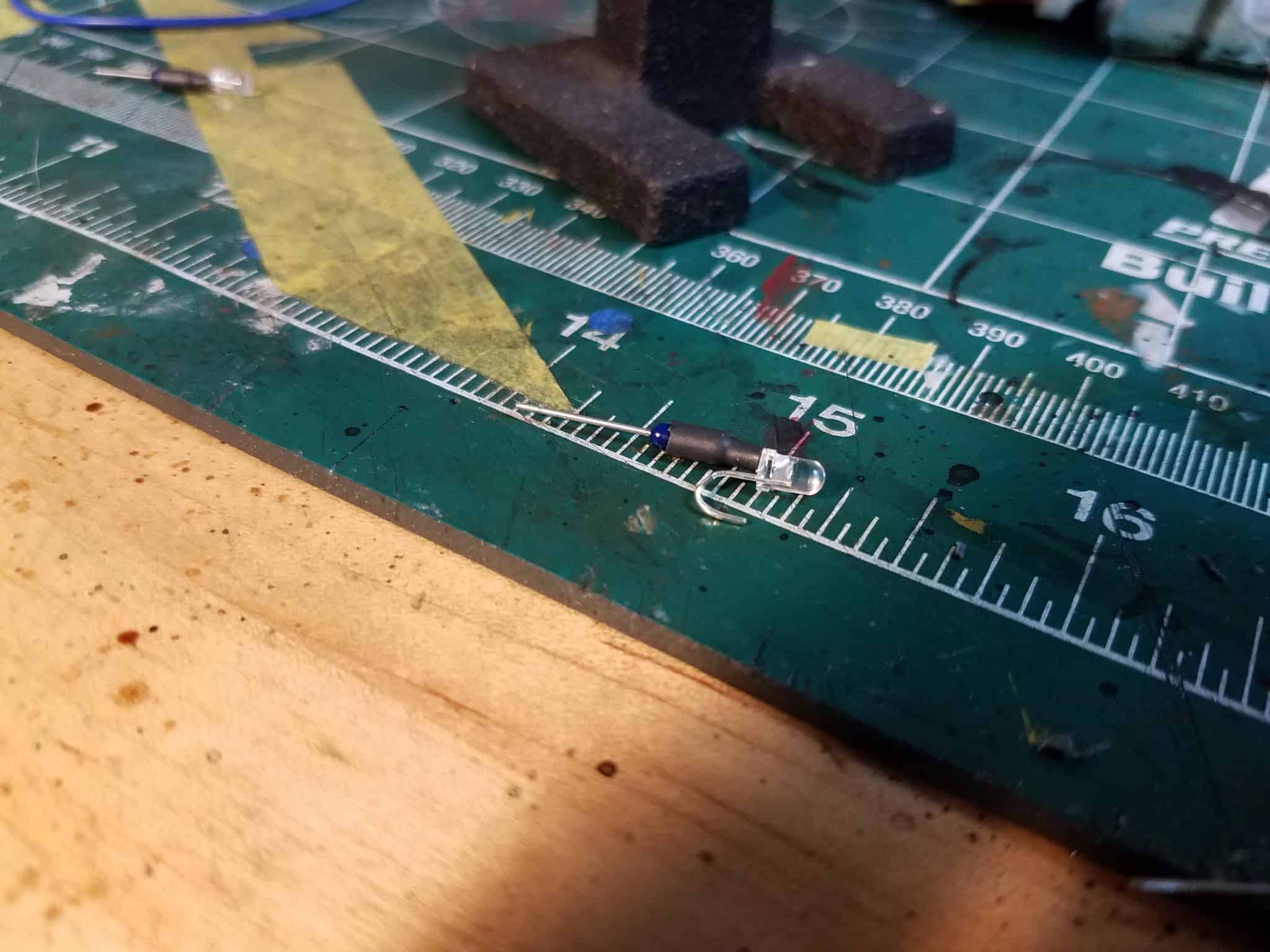
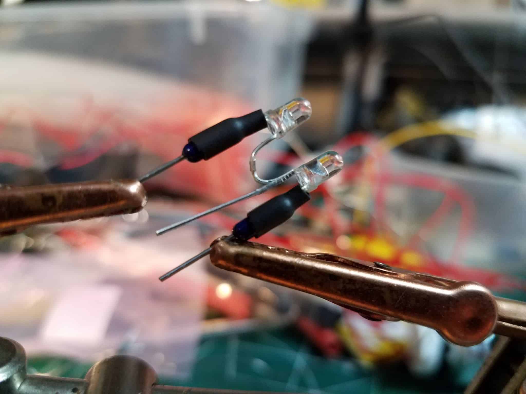
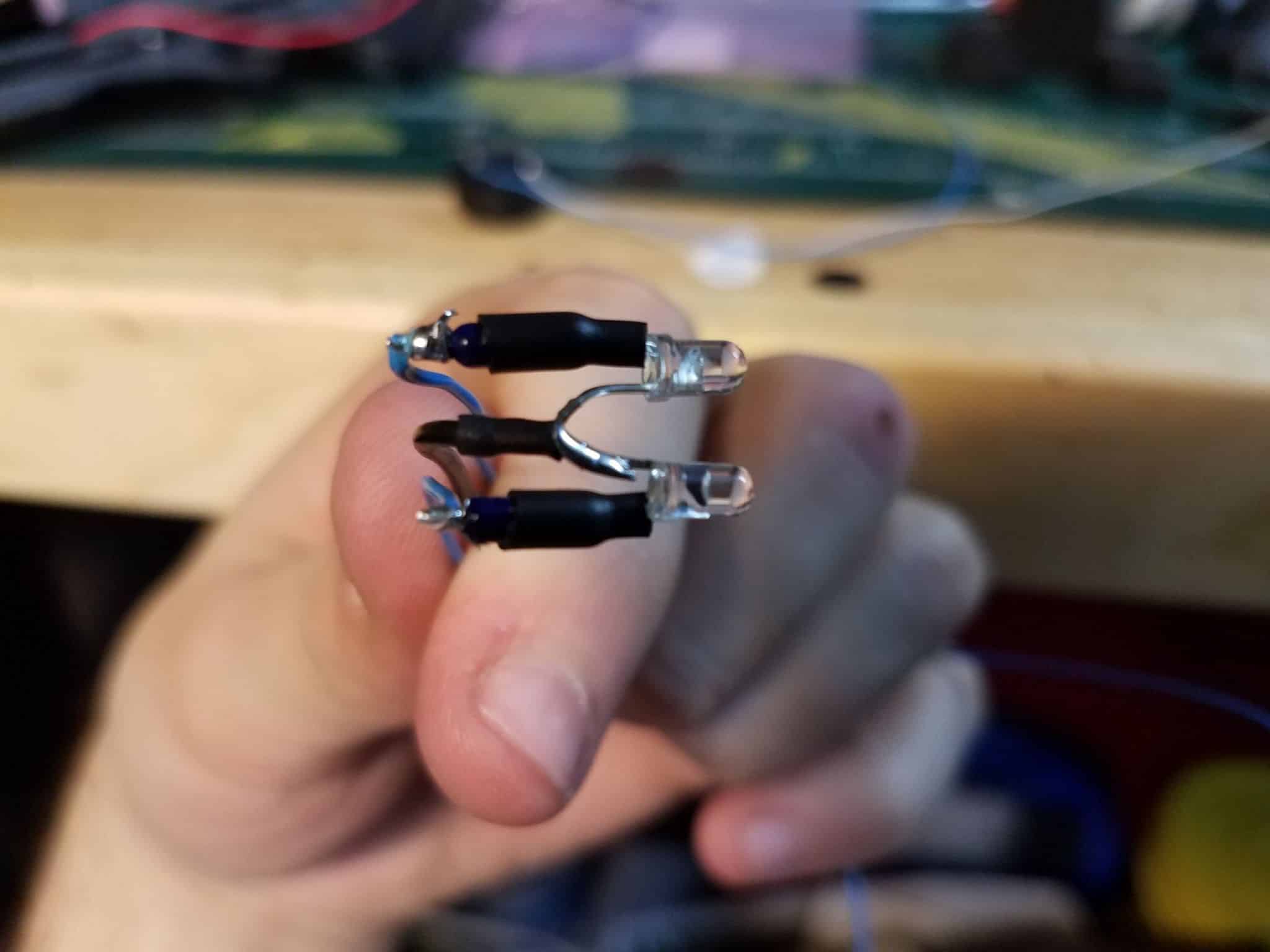
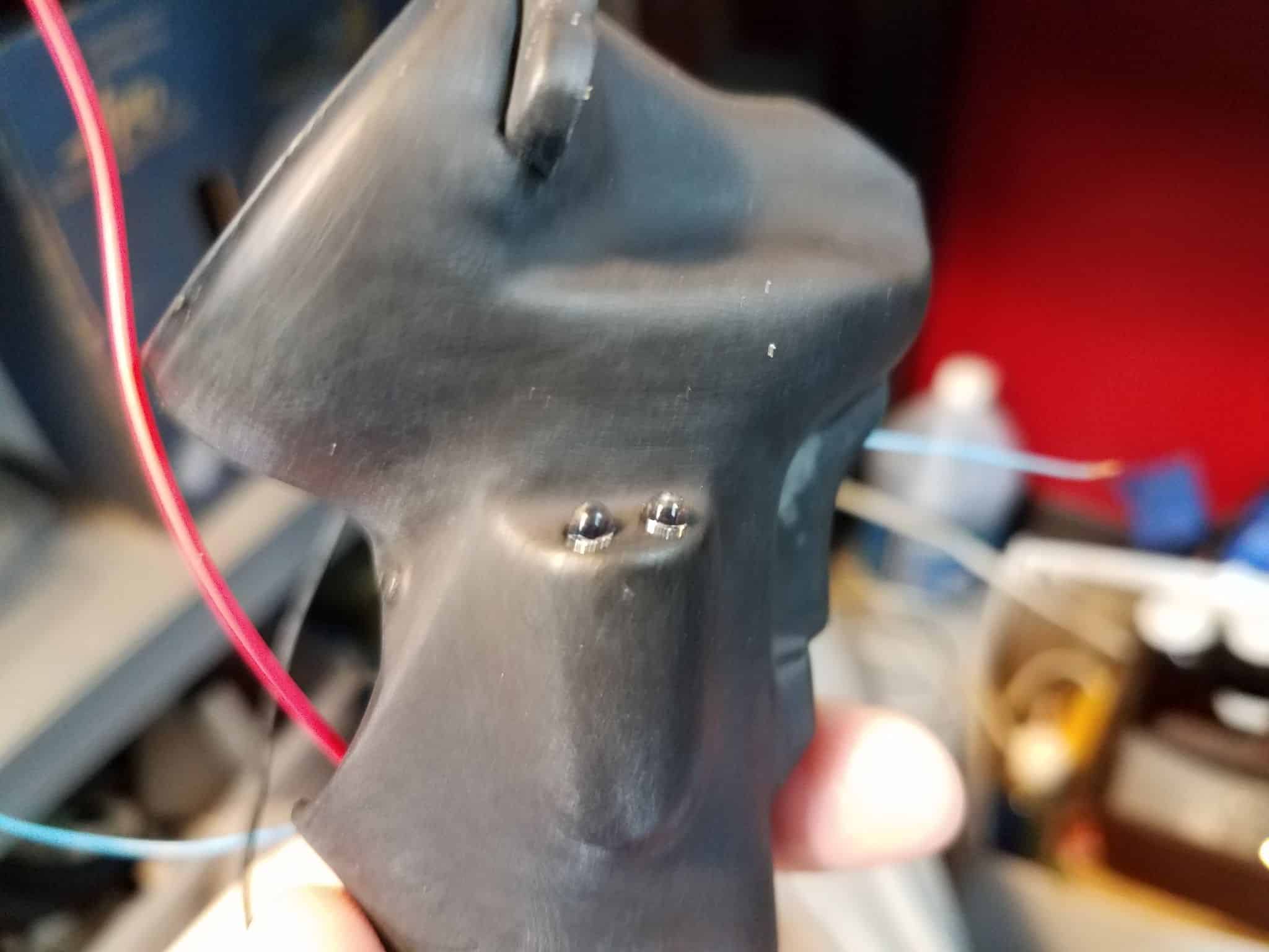
Next, since it’s going to be one of the harder areas to reach, we’re going to do the pair of 3mm blue LEDs on the side of the handle. These LEDs will generally run at 3.3v – 3.5v, but since I’m using a 5v arduino it’s a good idea to put a resistor in line with the positive leg of each LED. I’ve got a handful of 200 Ohm resistors kicking around my workbench that do the job well enough. I trimmed the leg, soldered the resistor on, and heat shrink wrapped them so that there was no chance of bad contacts.
I pushed them into place and squeezed a little superglue in behind them after I was happy with how far they were sticking out of the handle. Afterwards, I flooded the whole cavity with hot glue to fix them permanently into place.
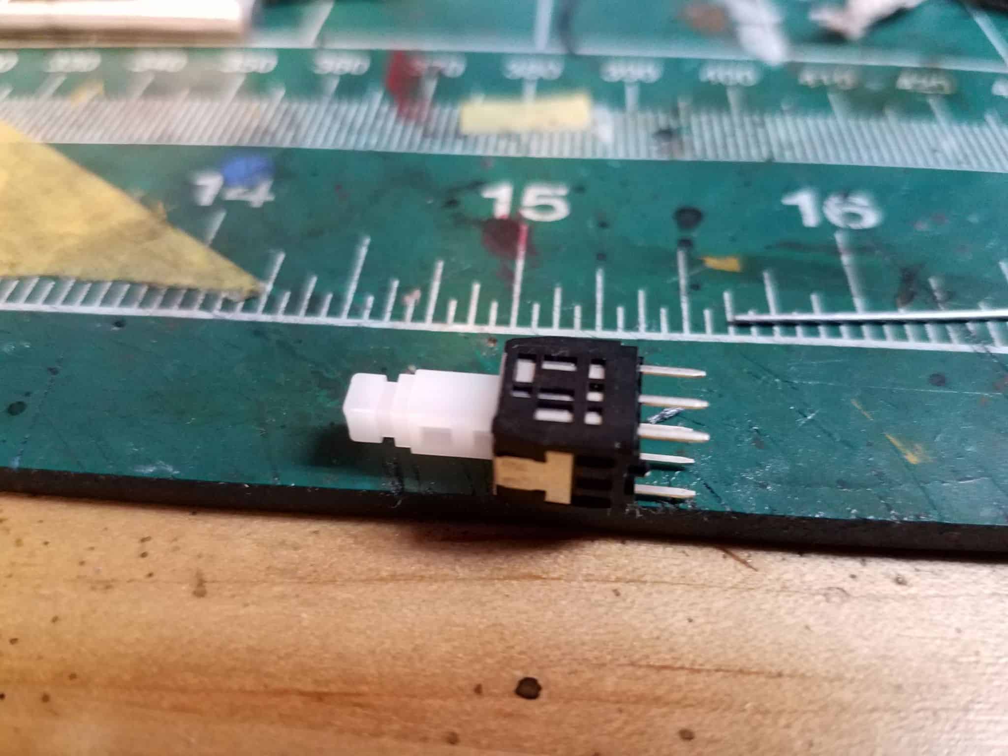
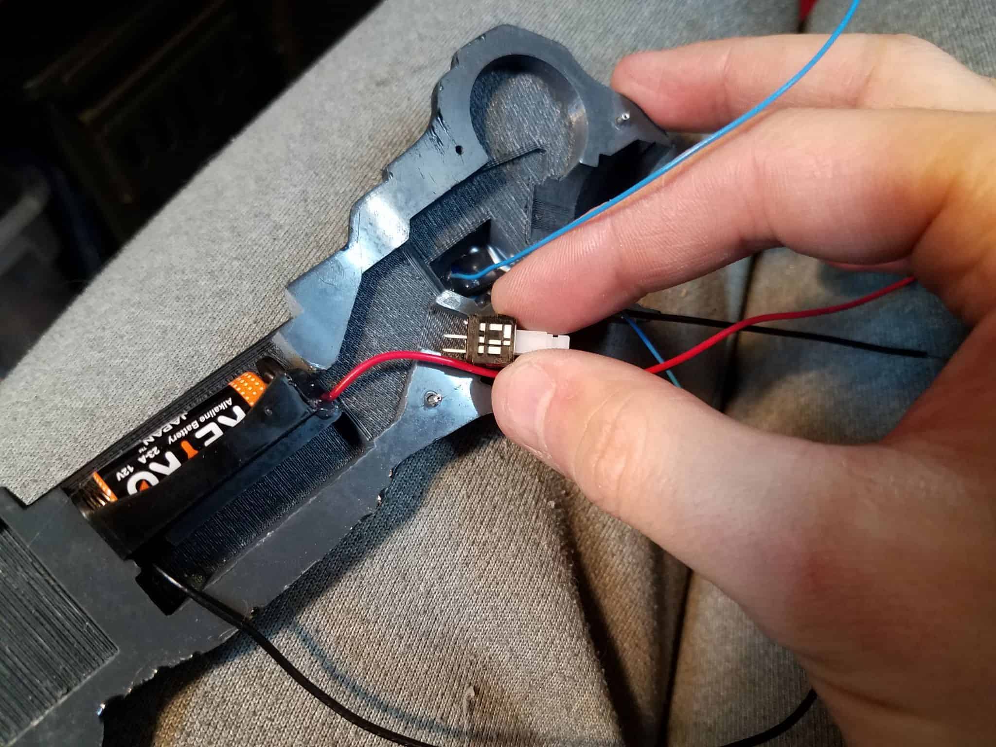
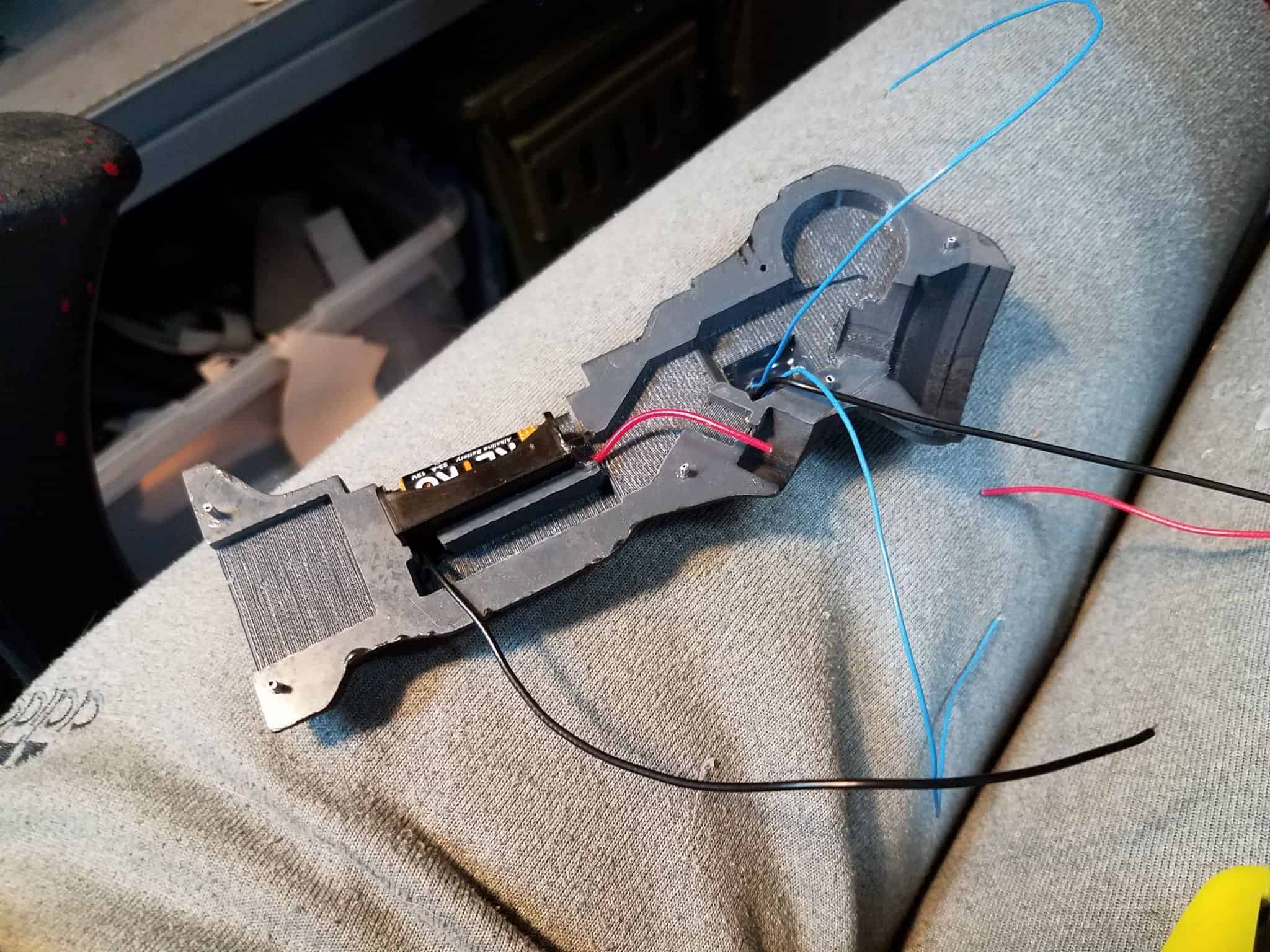
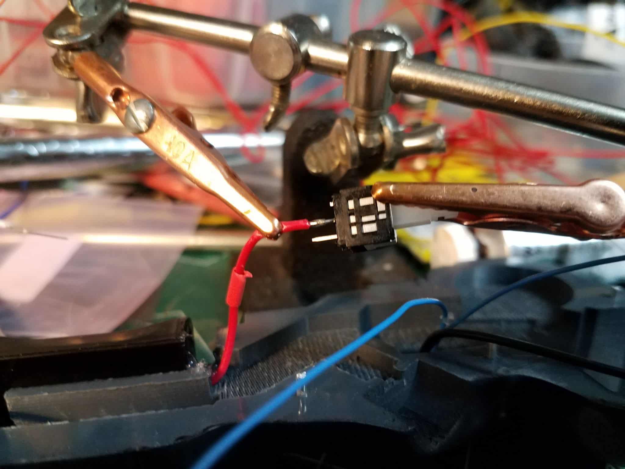
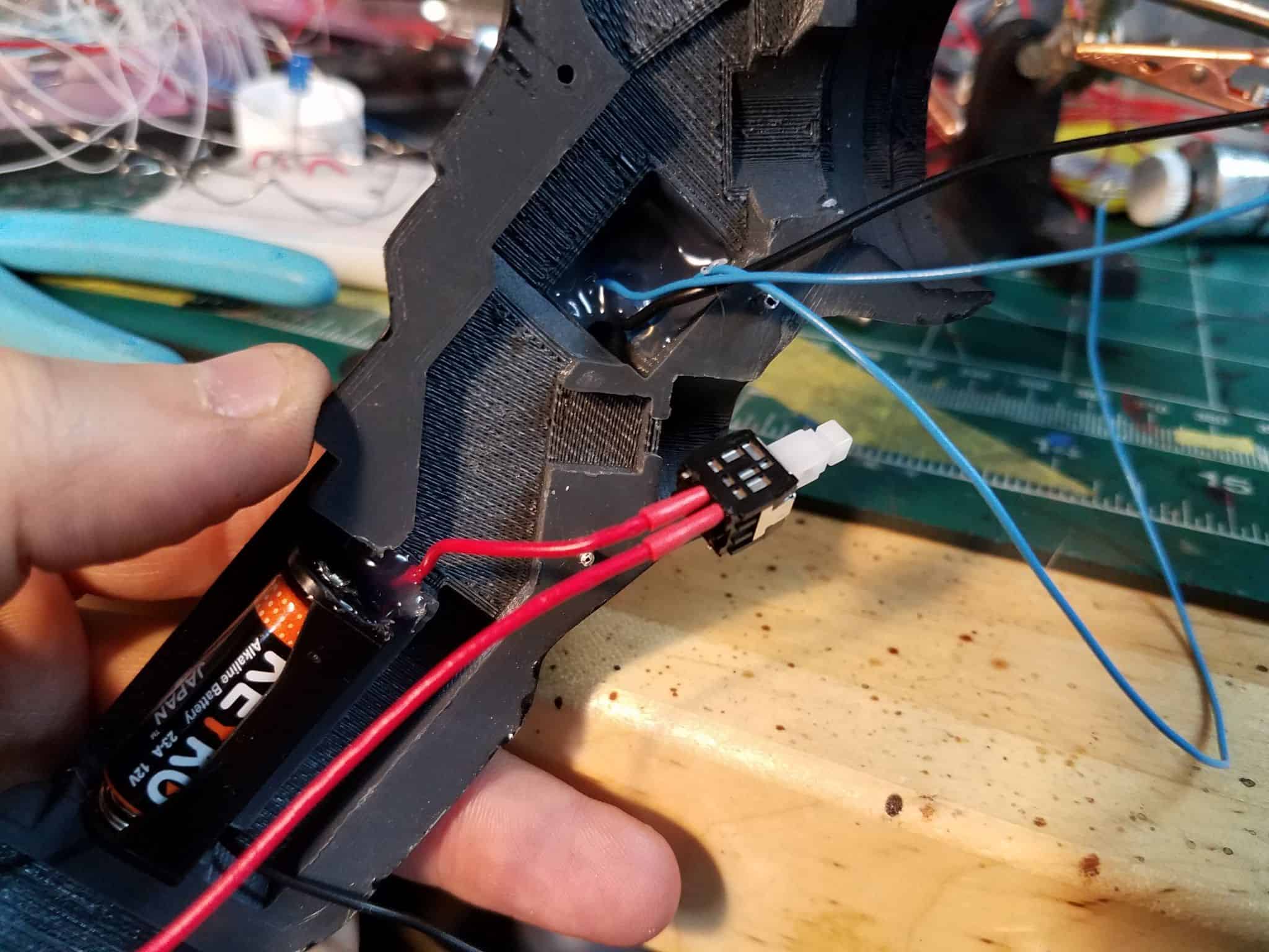
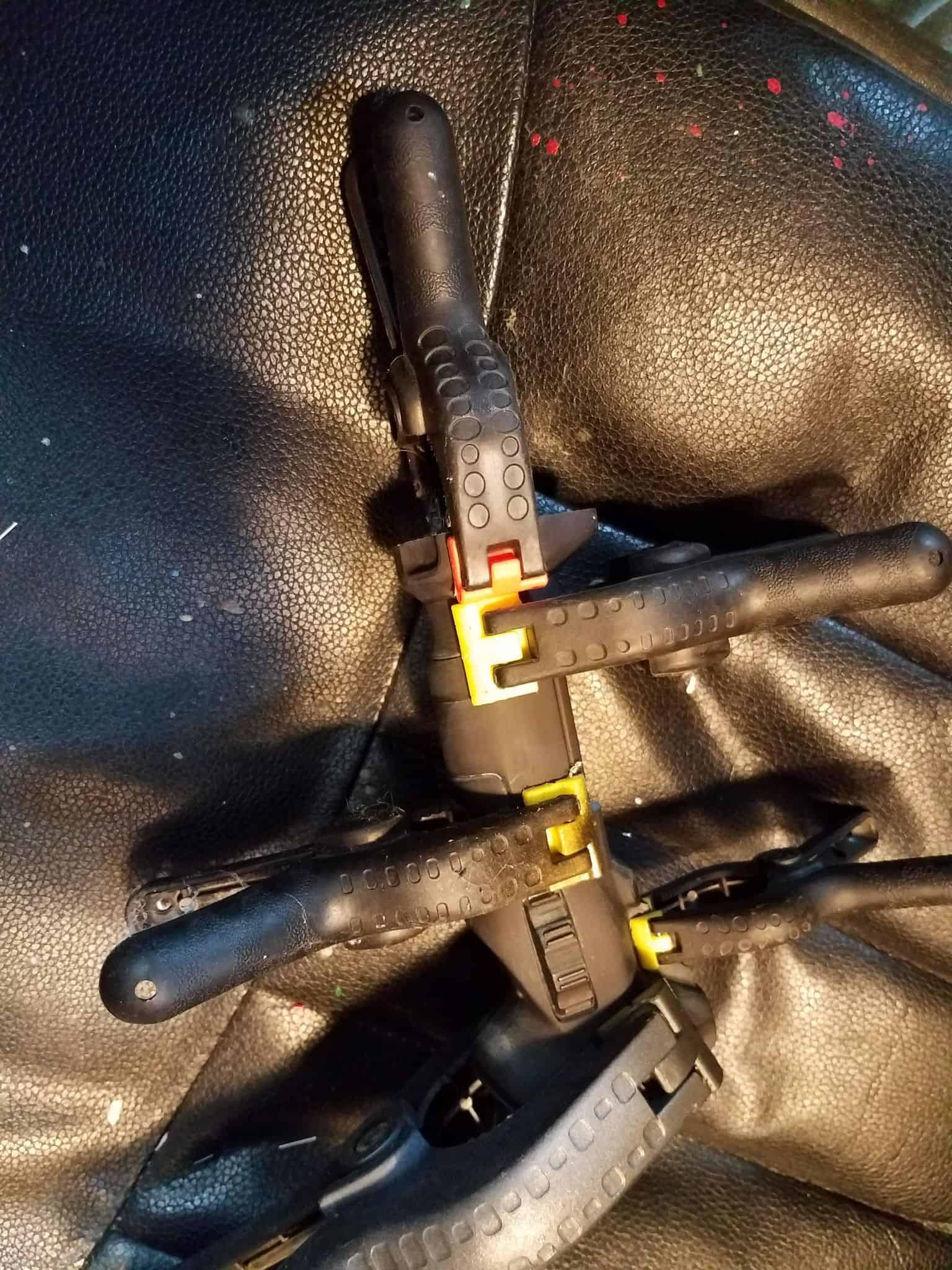
With that out of the way, lets take care of the power switch. The one in particular that I use has six legs, but that’s because it’s a DPDT switch, which is more than we strictly need. We can simply trim away the unnecessary legs for this.
Size it up with the spot you are installing it, so you can get an idea of how short you’ll have to cut the red (positive) wire from the battery compartment. Then solder your connections!
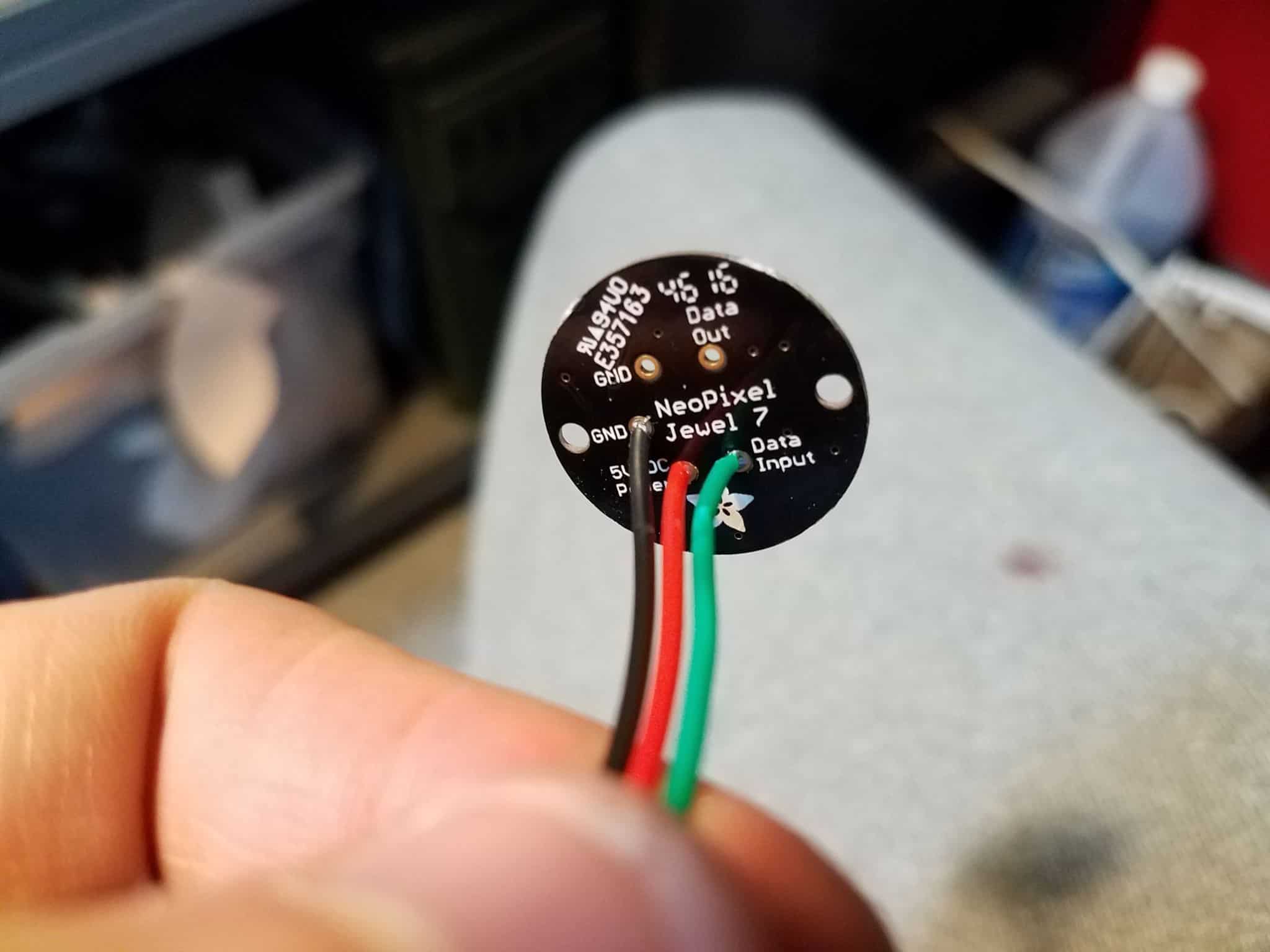
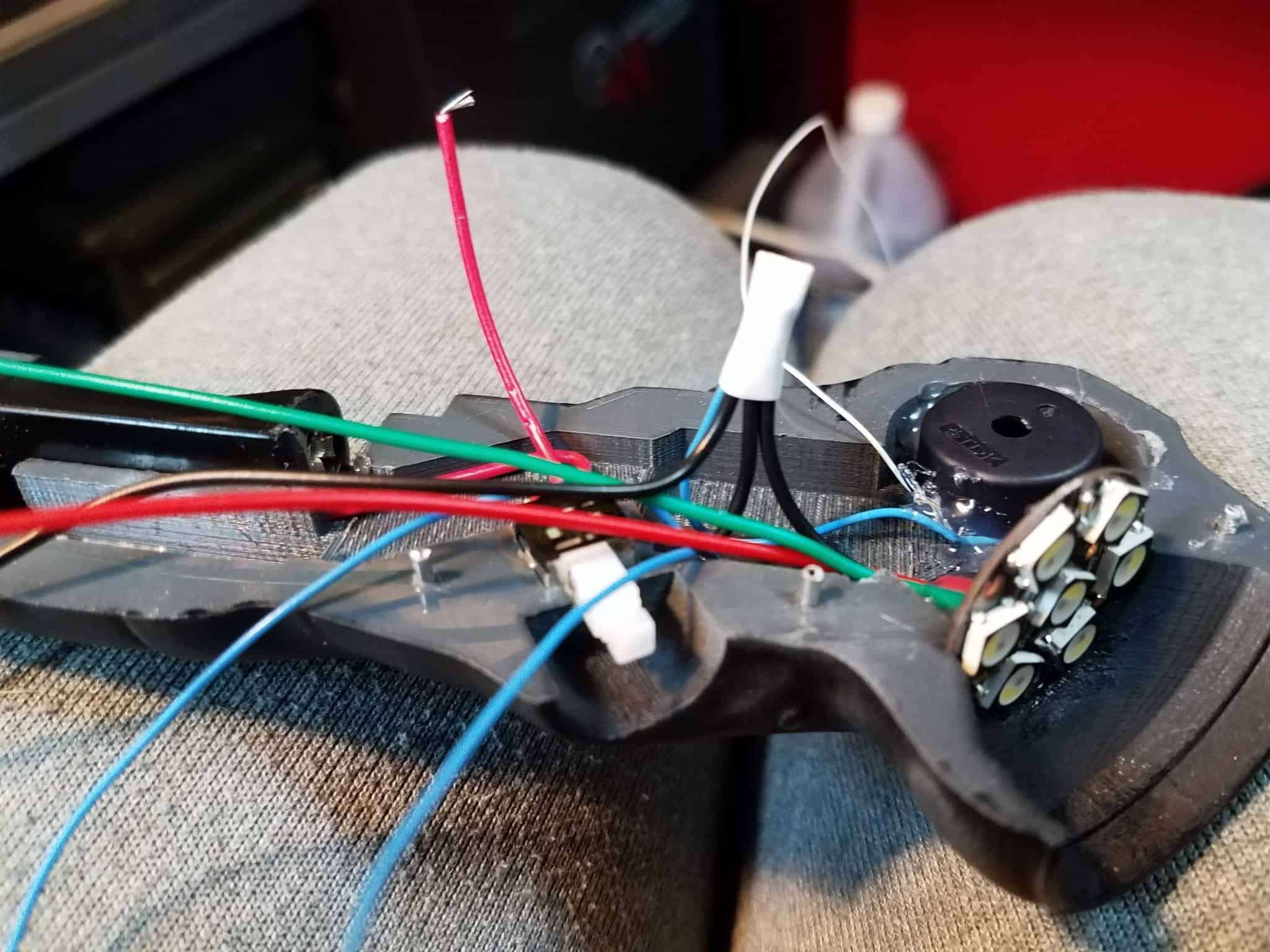
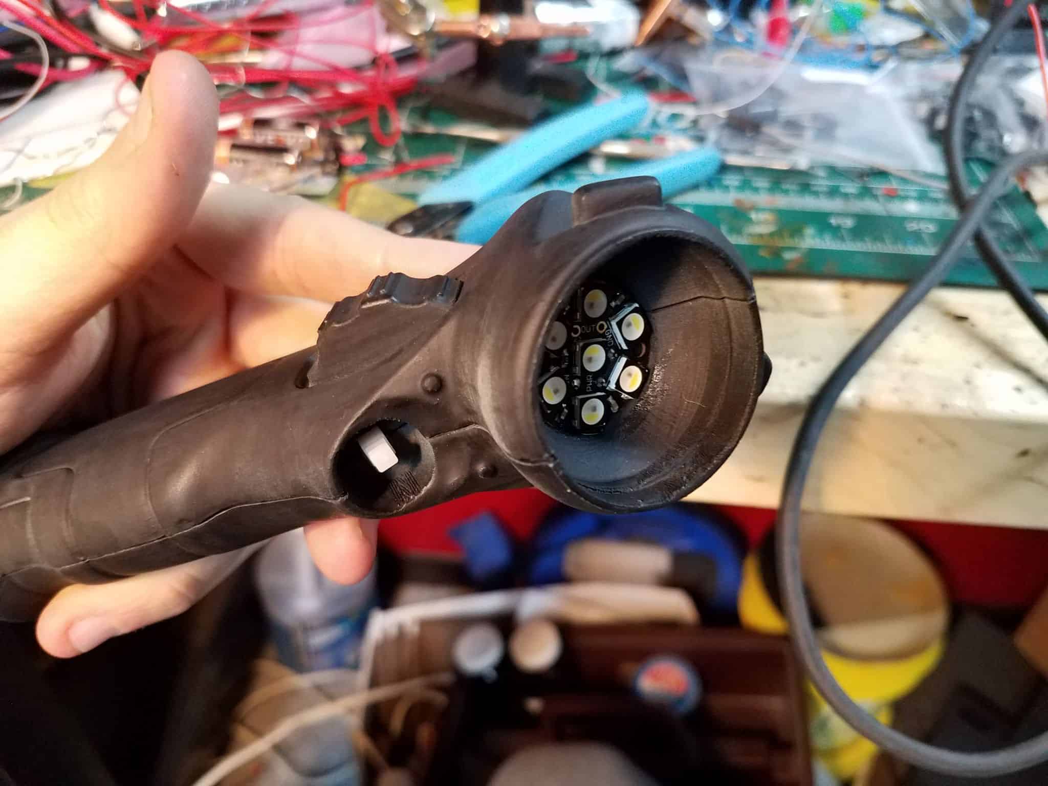
Installing the Adafruit Neopixel Jewel is up next. Solder your wires to the disc – red for 5v in, black for ground, green for data control.
I superglued the Jewel into place, then hot glued the back of it to give it a bit of extra hold.
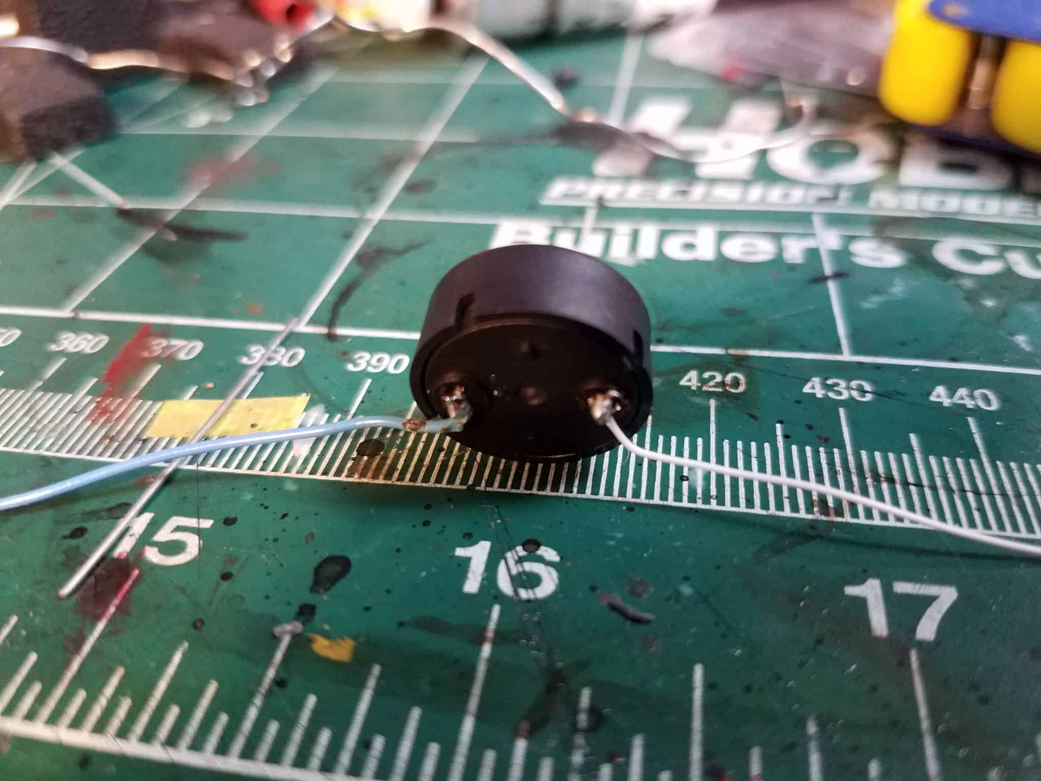
The Piezo buzzer I used for audio on this particular knife was not the same as the last one – this time, I used a PS1740P02E. After testing a few options, this one was the loudest and had the best fidelity for the audio frequencies I had chosen.
I soldered some thin wires to the back of the piezo…
… then superglued it into place and filled the space around it with hot glue again. Keep the hole facing up, since this is where the sound comes out of and if you put it right up against the flat surface of the inside of the knife it’ll sound muffled.
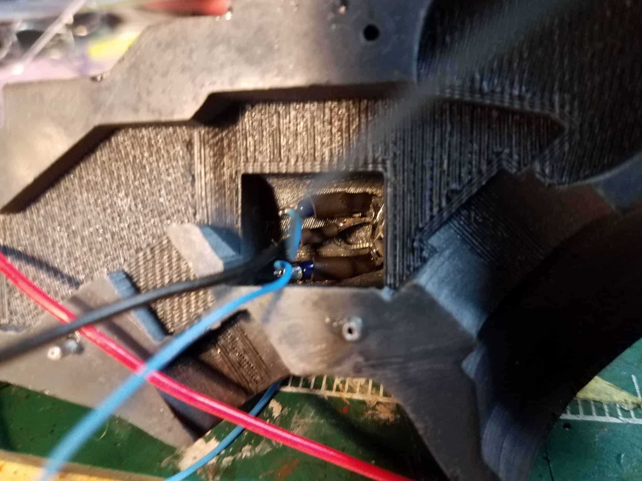
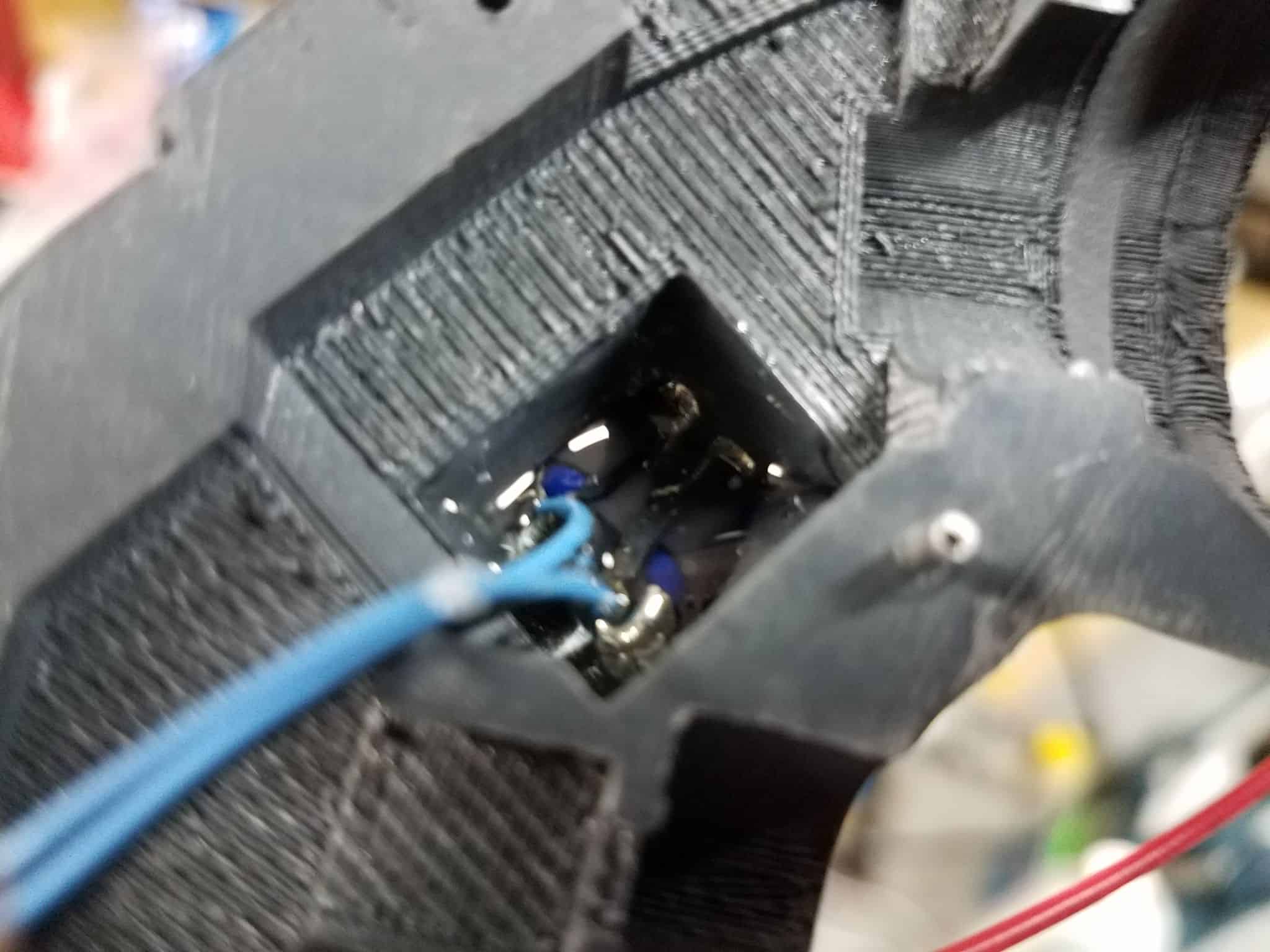
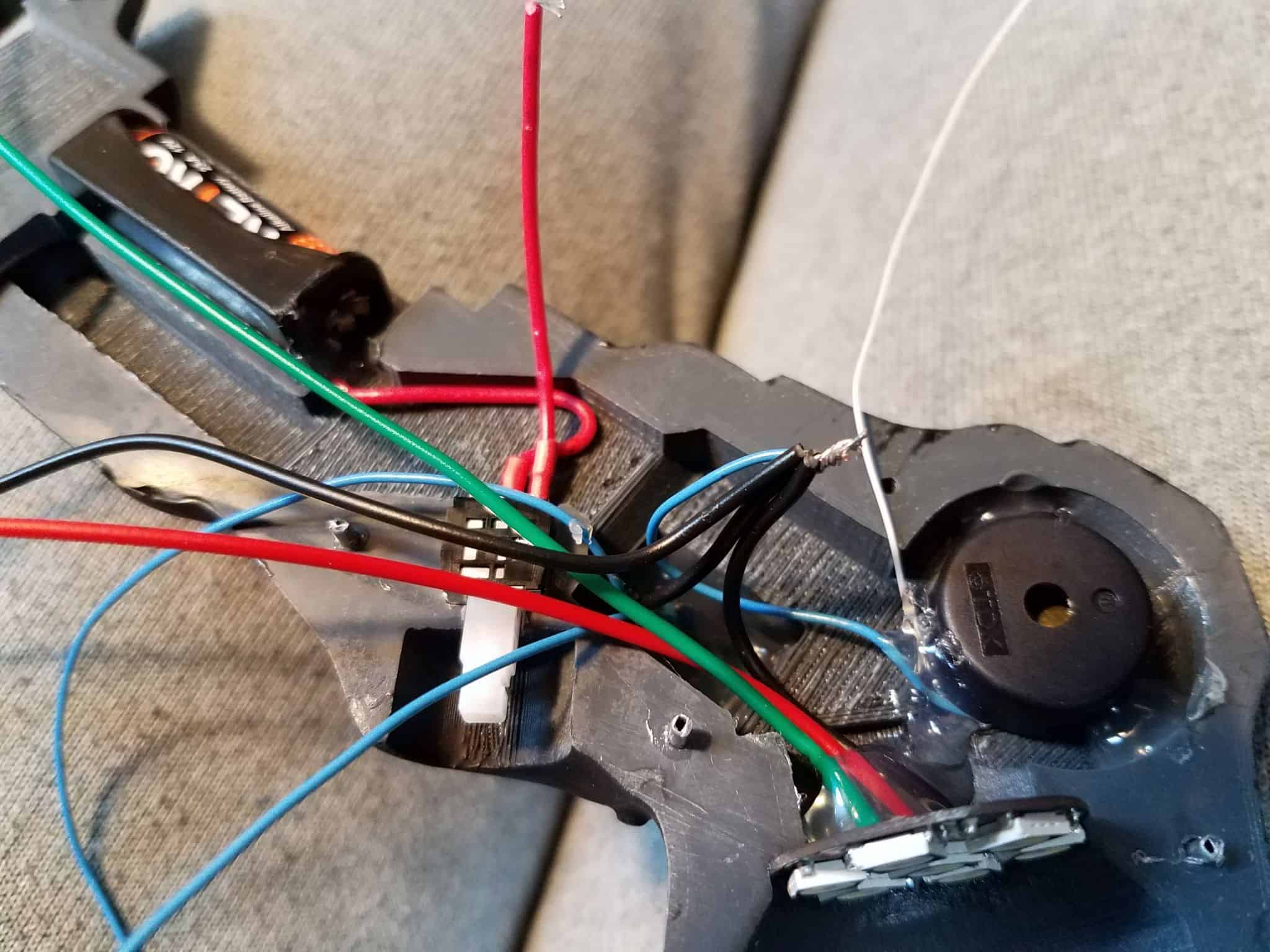
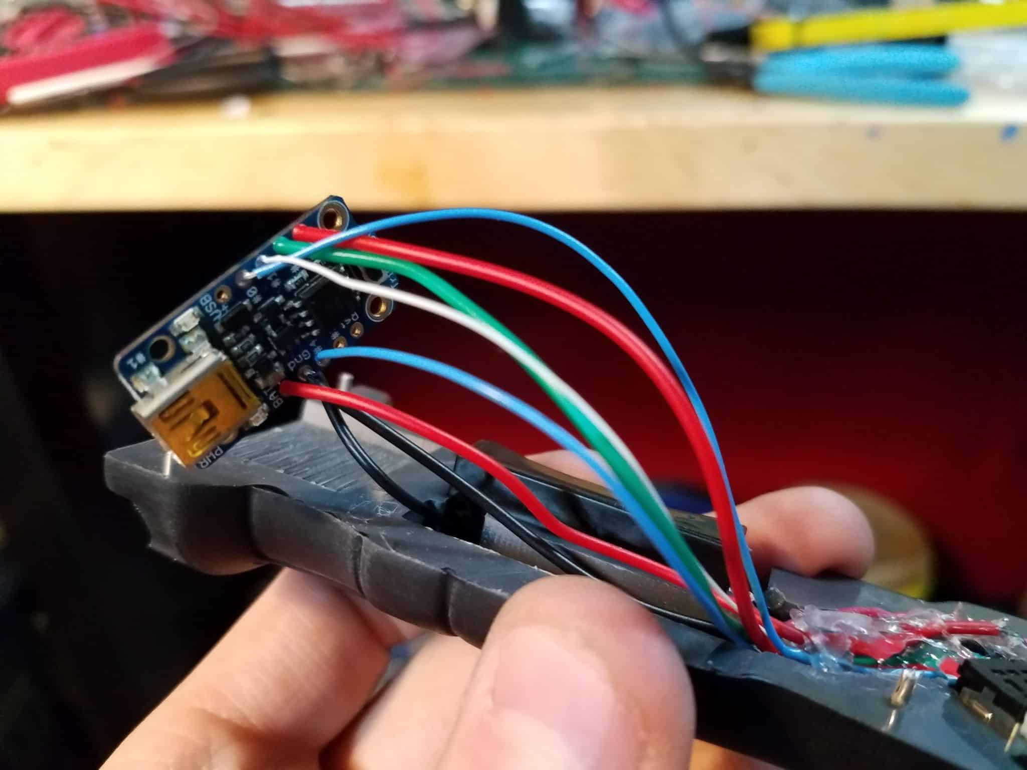
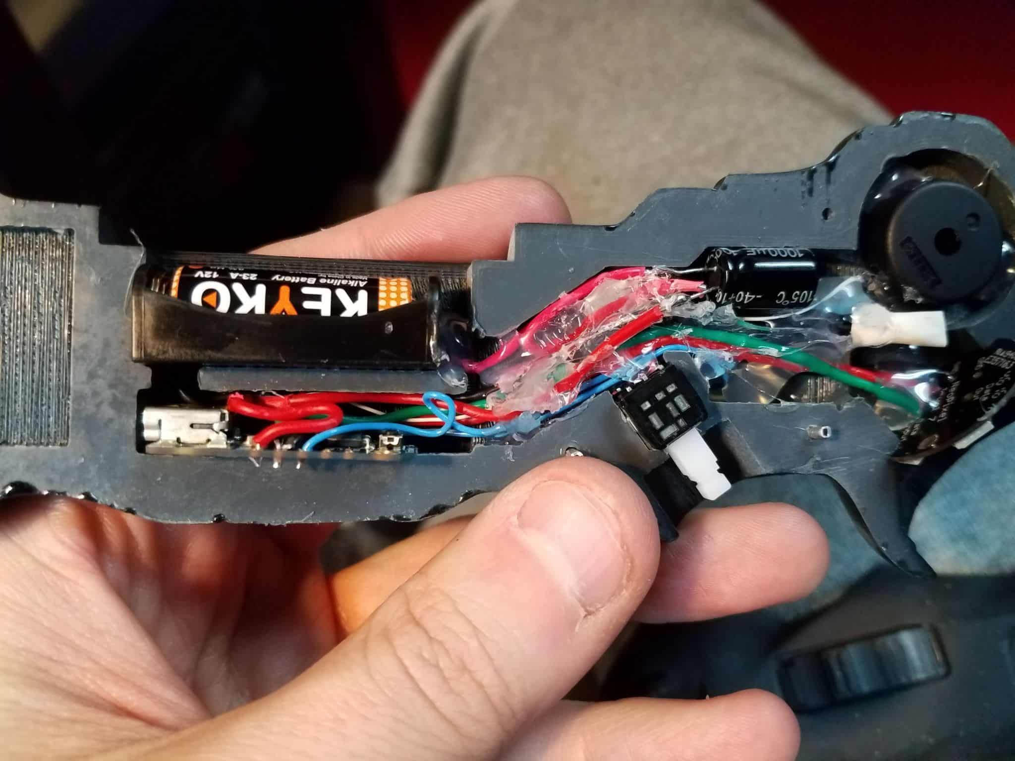
With all these components into place, it’s time to consolidate some things. The Jewel, the Piezo, and the 2 LEDs can all share a common ground, and all of these wires pass through the main cavity of the knife, so grab them, cut them short, strip them, and twist them up. Heat shrinking wires like that helps keep things sane, because god help you if things ever start touching that aren’t supposed to be touching while the knife is closed up.
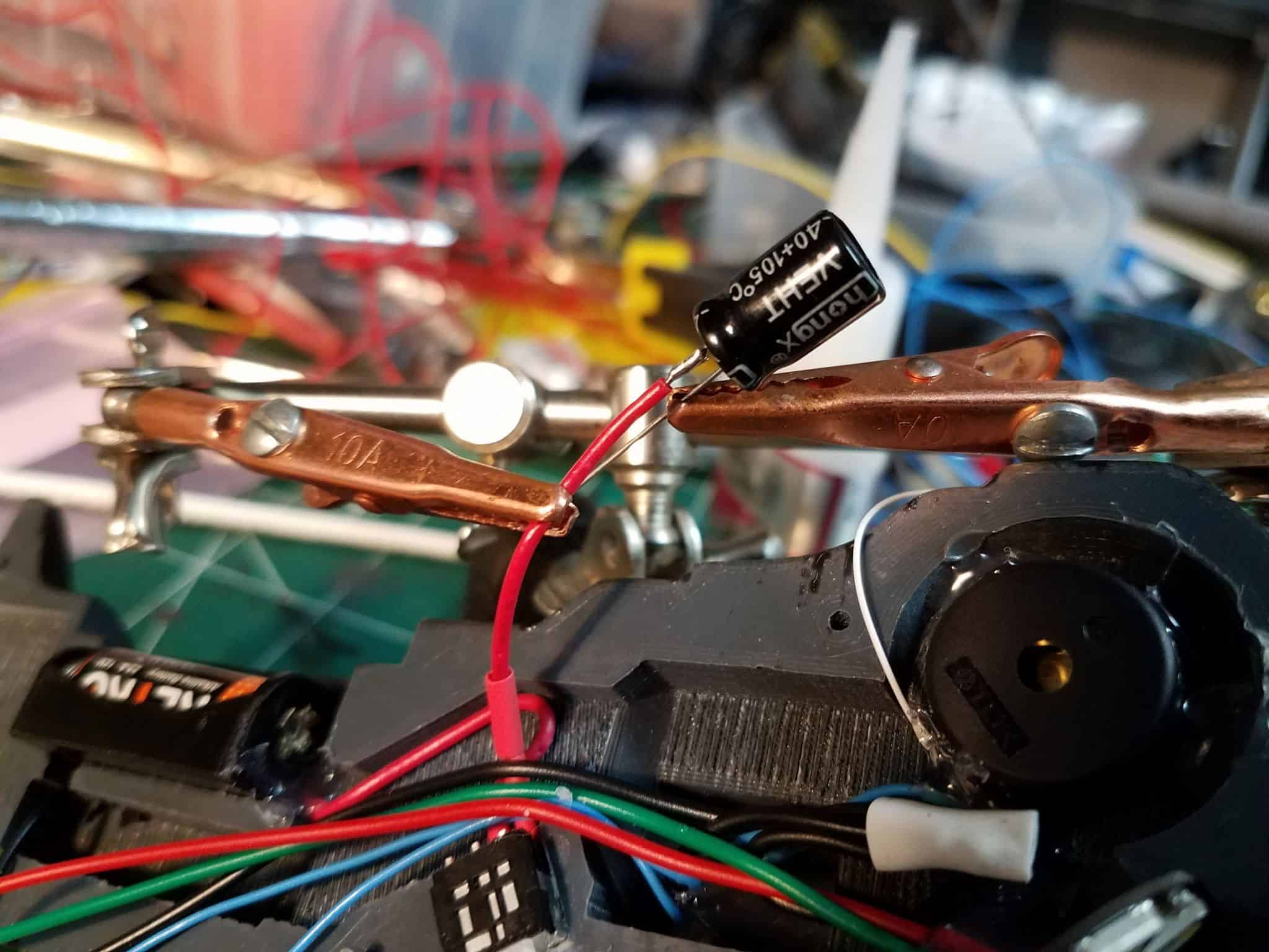
Now, on my first knife, I simply connected the positive line from the switch straight to the arduino. I noticed that when the battery started running low, the arduino would sometimes ‘reset’ when the Jewel lit up, because the power draw was too much for the dying battery. This time, however, I took the time to insert a 1000uF capacitor between the switch and the arduino. This should help with some of the power spikes that the Neopixels can cause when they are fully illuminated, and is advised as best practice with Neopixel products on Adafruit’s site.
Capacitors are sensitive as all hell to heat. Handle with care, and test the voltage and connections before you go any further. I’m glad I did, because I discovered that the capacitor in question I had used was damaged, and was only putting out around ~3V. I was able to quickly replace it and get on with my life, but I would have hated discovering that late.
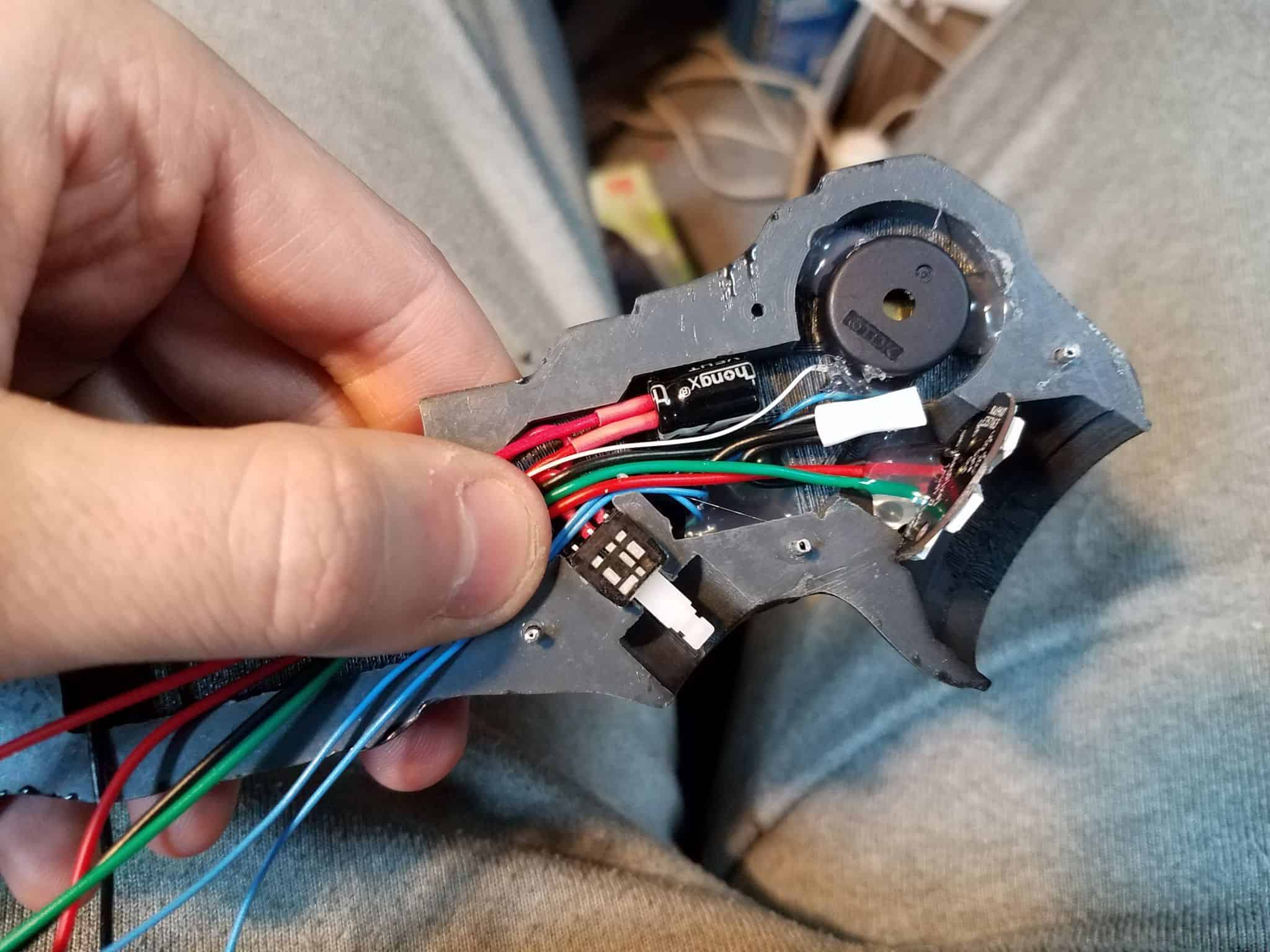
You should be able to, at this point, lay all of the component wires down and adhere them to the inside of the knife with hot glue. Again, don’t hot glue the capacitor directly, or you could overheat it (like I probably did). You’ll have to trim wires to the appropriate length so you don’t end up with too much to close the body of the knife up. I started with the ground wires.
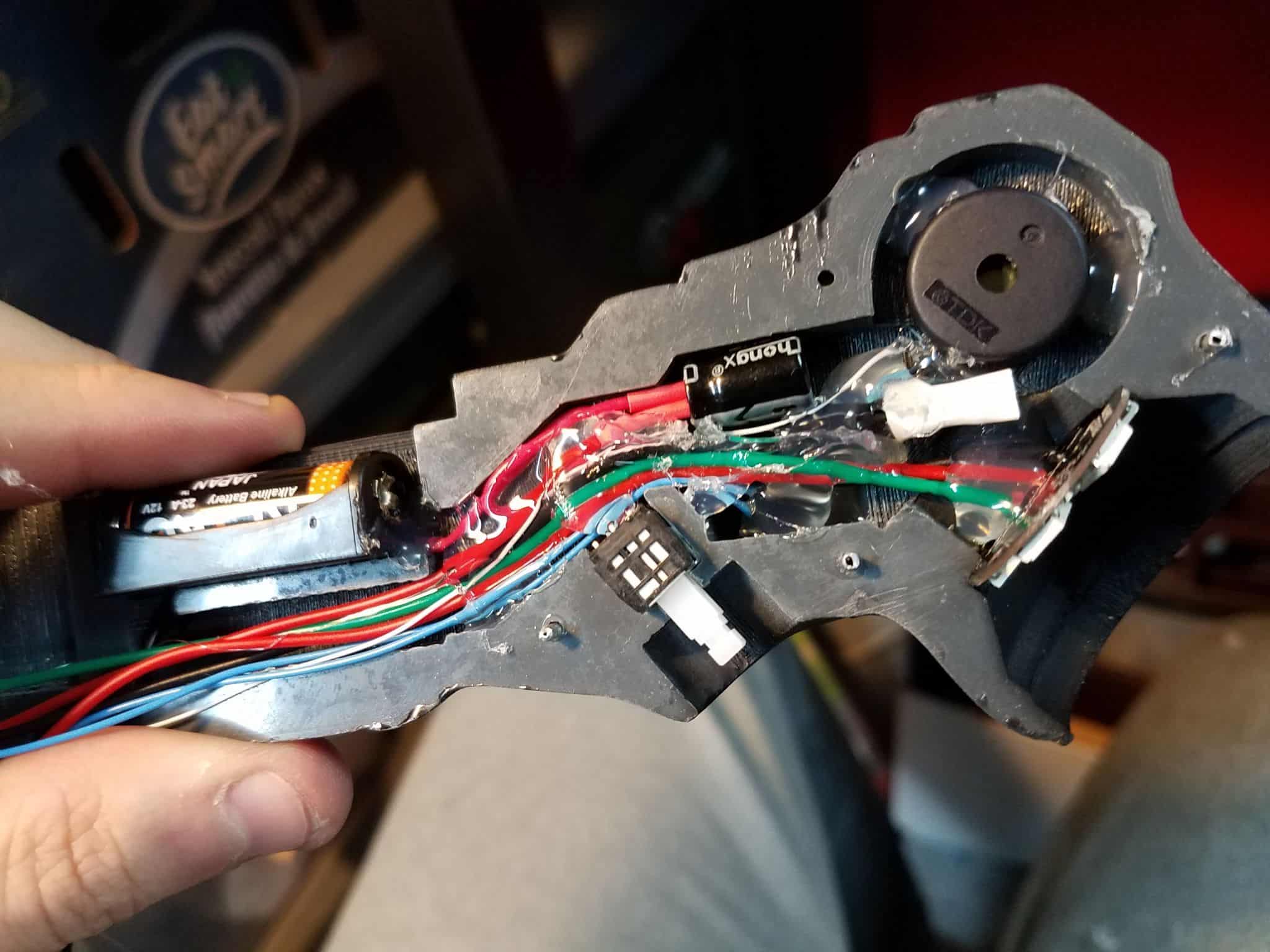
That’s it, baby! You’re done! You should be able to close the two halves of the knife up – do a test fit. Once you’re satisfied, superglue the two halves together. I clamped the hell out of mine, but you’ll still have to work on patching the seam on the outside of the knife afterwards.