Author's NoteThis post is fairly outdated - I've made a lot of revisions and improvements to Star Lord's earpiece design since initially putting these instructions up. Nevertheless, I thought it'd be useful to leave this information up for posterity's sake, or in case it might help someone else out.
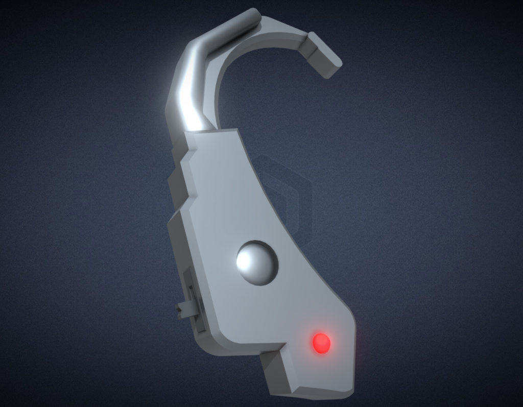
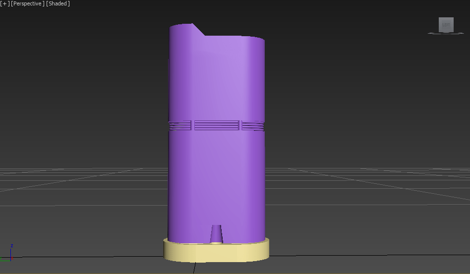
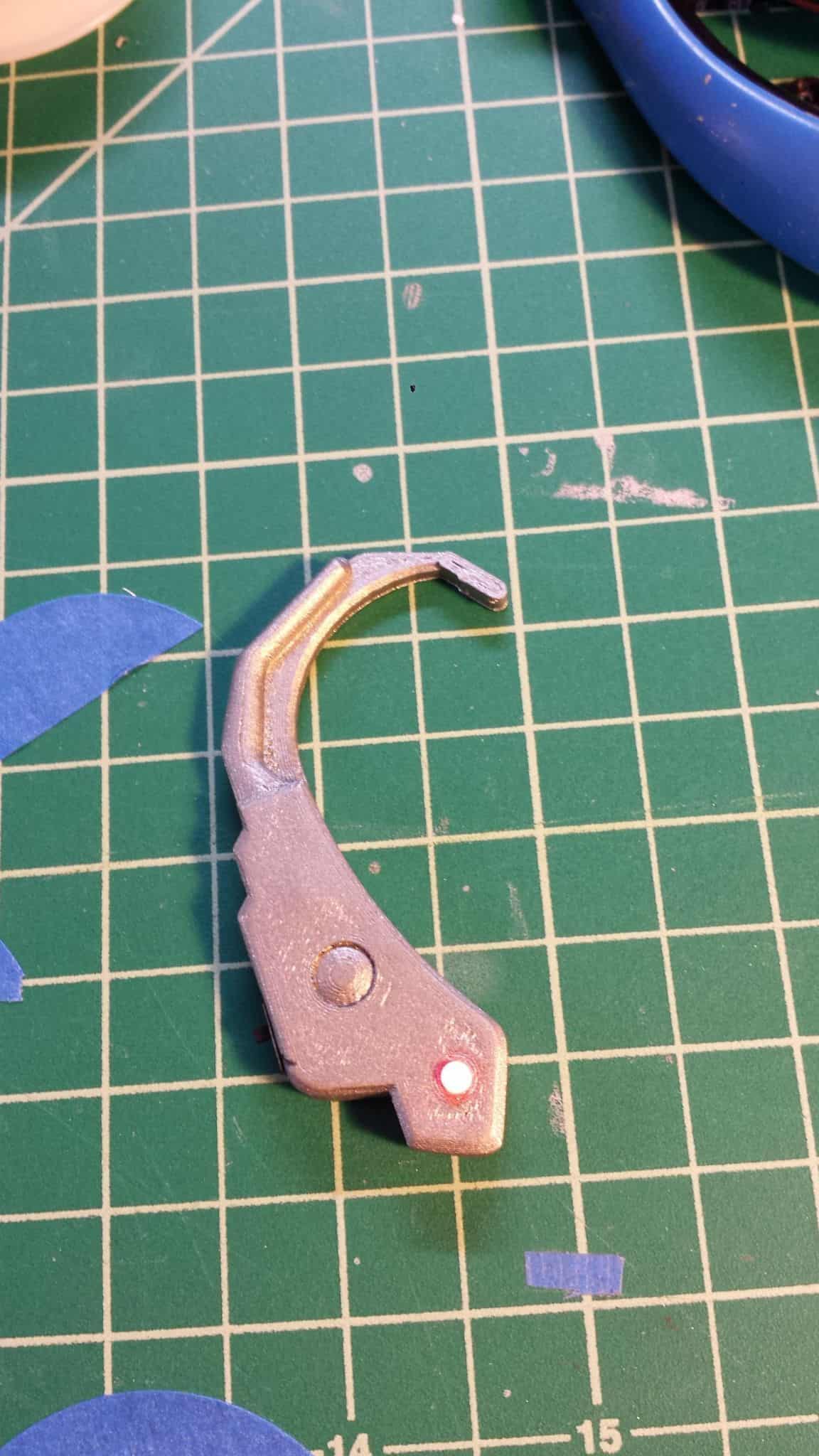
Here’s a quick step-by-step for Star Lord’s earpiece. I popped this one out of my 3D printer as a demonstration piece and have only hit it with silver spray paint for visibility’s sake, so know that the final quality of the product should be better than what you’re seeing below.
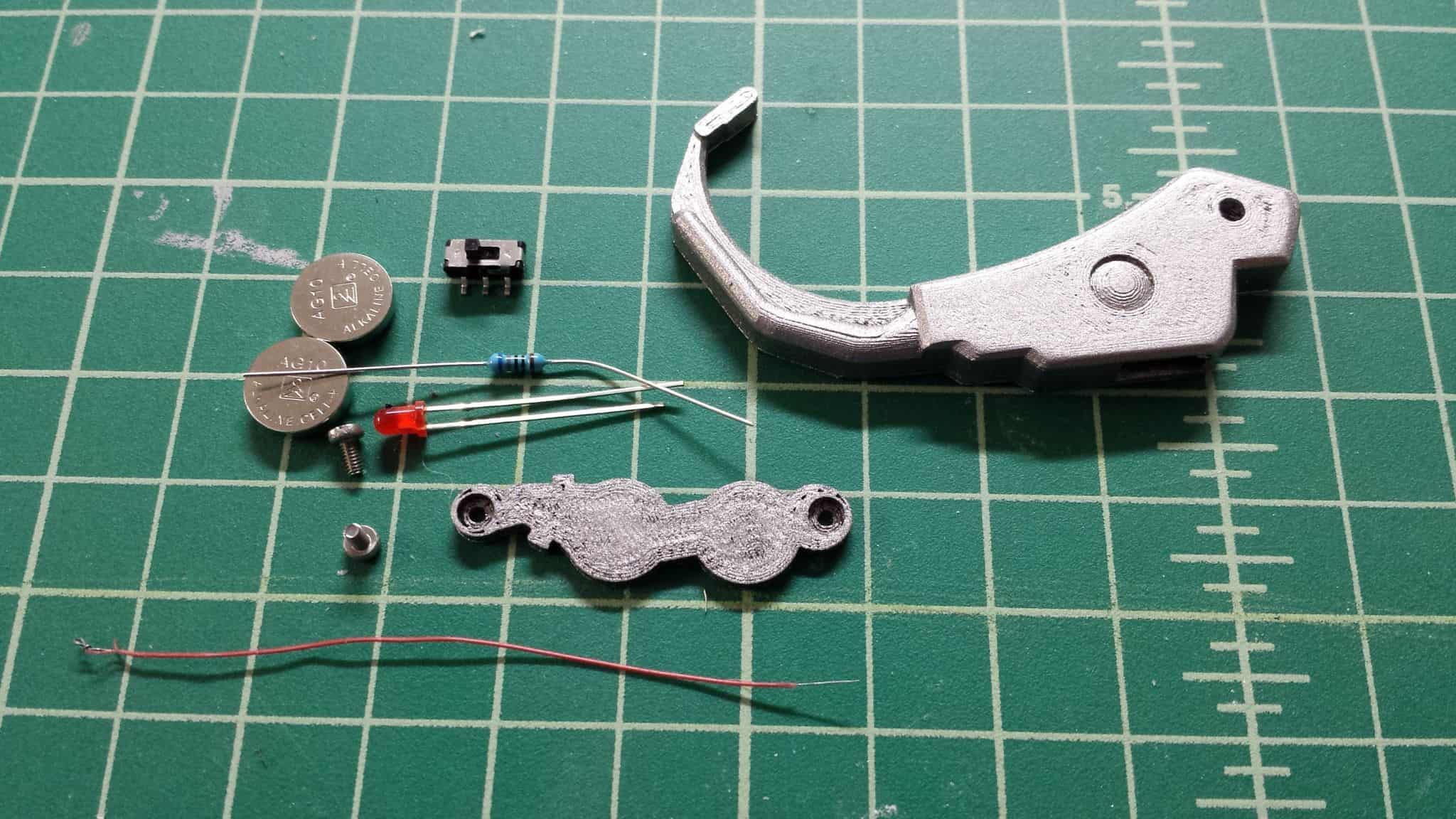
Let’s start with the list of materials.
Earpiece;
3mm red LED;
Two (2) M2x4mm screws;
Two (2) AG10 coin cell batteries (aka LR1130 batteries, depending on manufacturer);
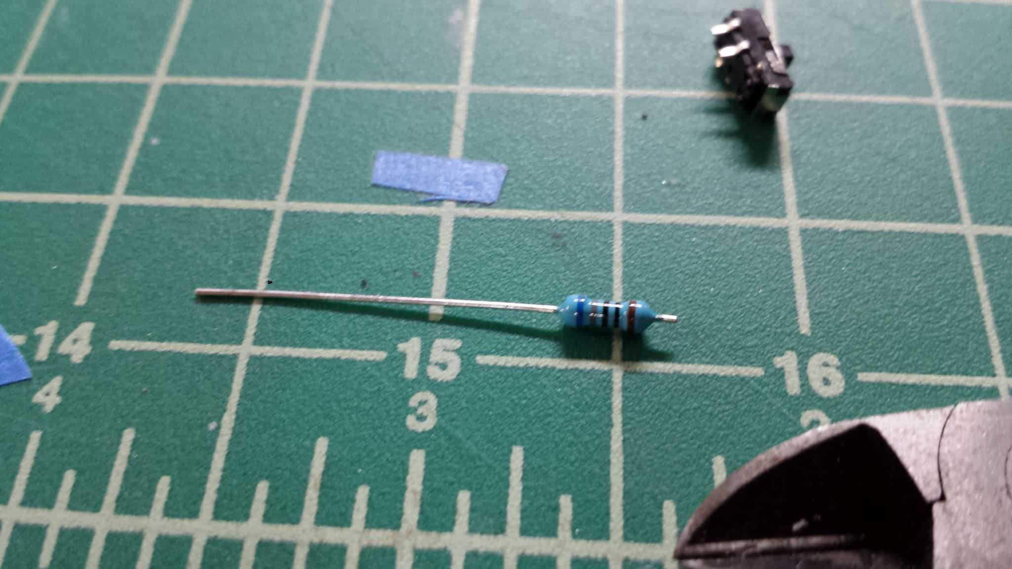
One (1) resistor – ballpark 60 Ohms will do.
Thin wire; and
Switch.
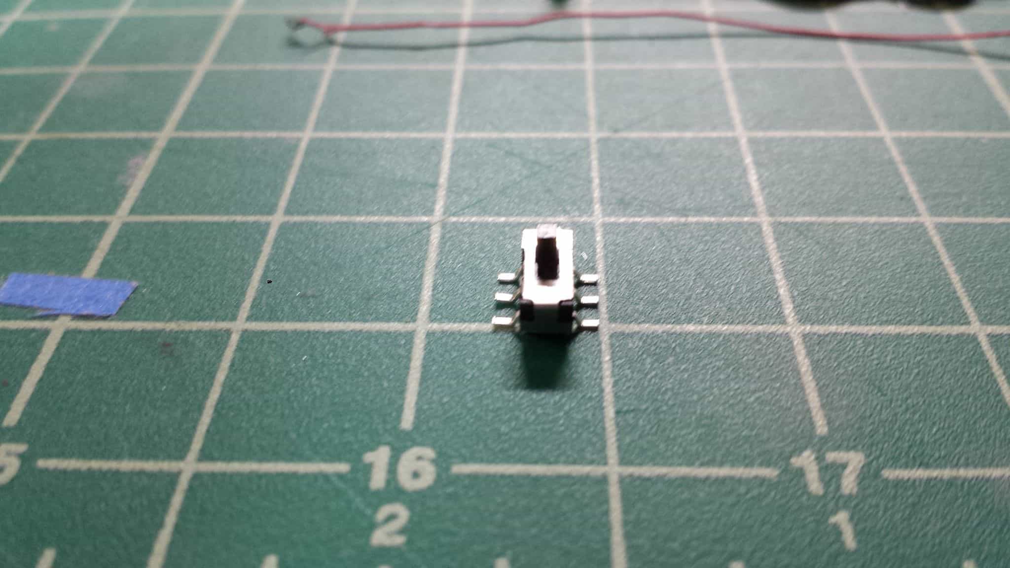
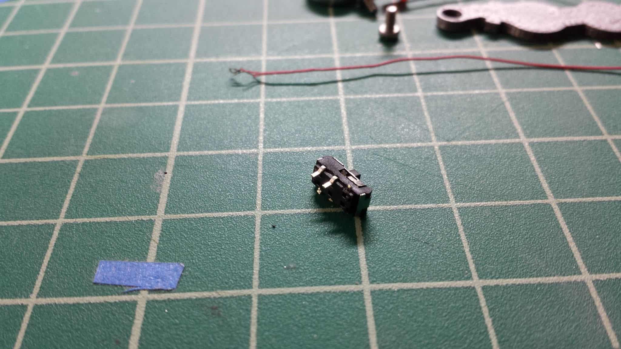
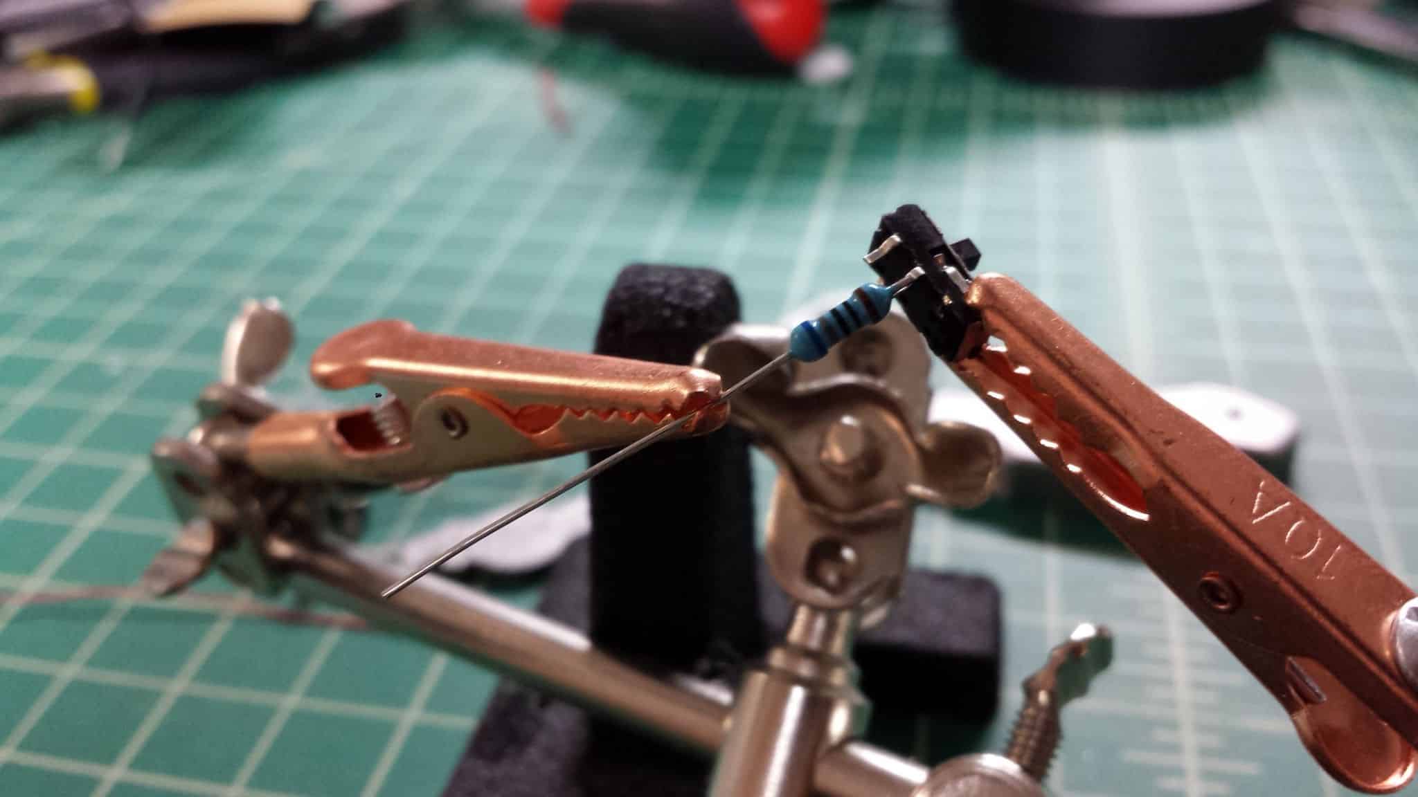
First thing we’re going to do is trim the unnecessary legs off the DPDT switch, effectively making it an SPST switch. I mostly modeled this thing around this switch because these switches are cheap and readily available.
Those two legs I have left will join the circuit together when the switch is in one position, and break that connection when it is in the other position. Your switch may vary, so make sure you check the legs before you cut them!
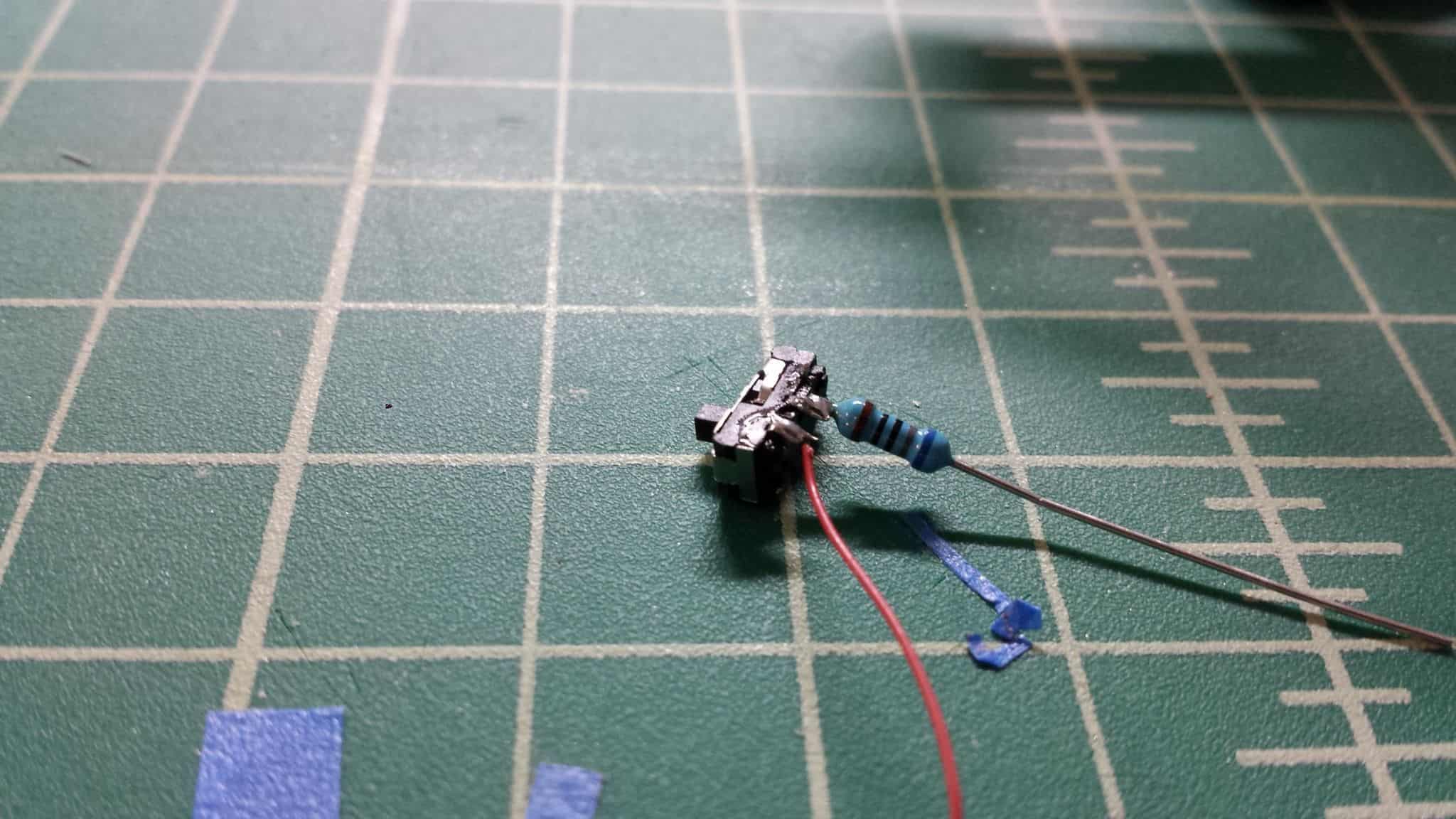
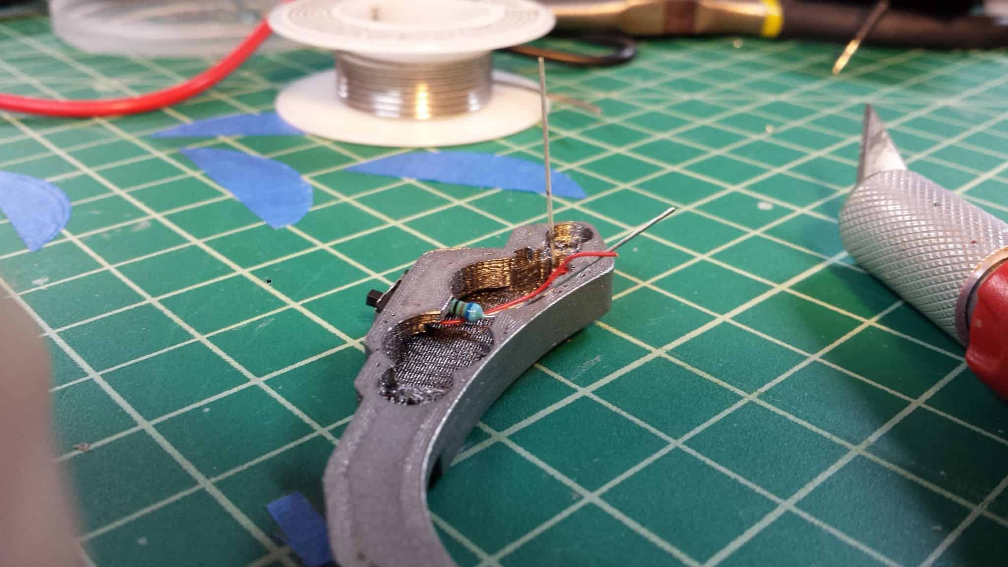
Snip the resistor down good and short, then solder it onto one of the remaining legs of the switch, with the wire on the other leg.
Ugly soldering job, that! But it works.
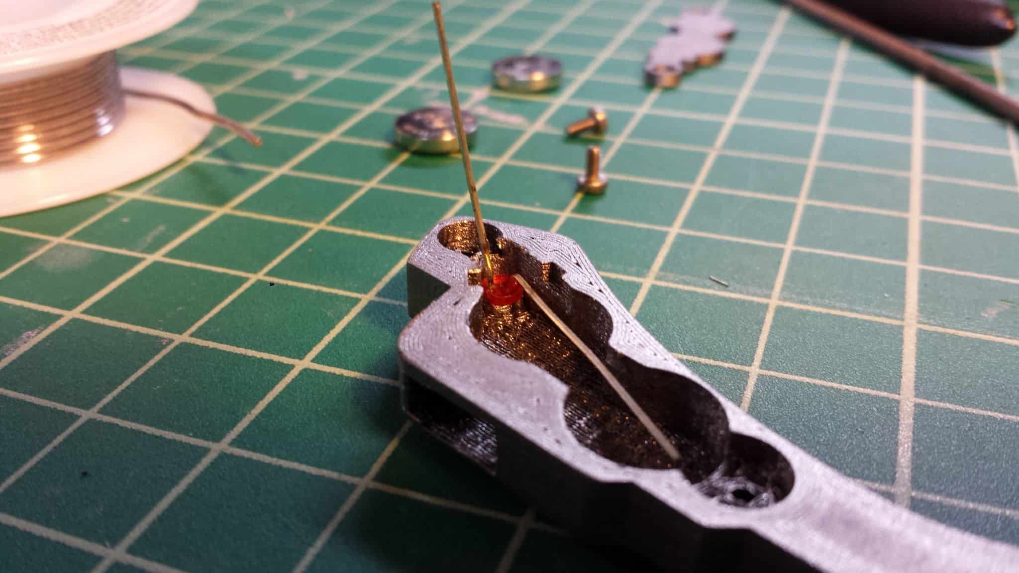
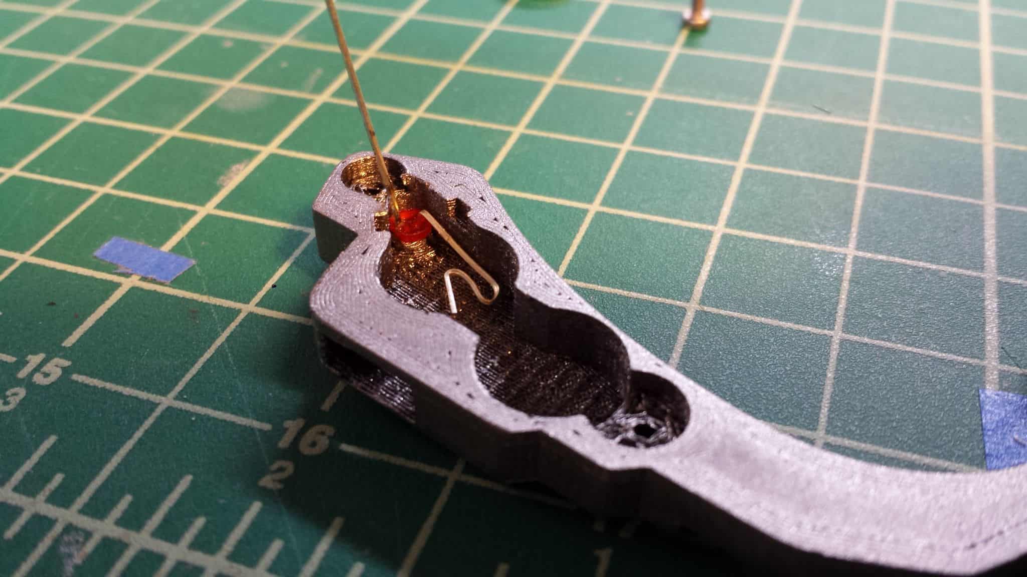
Next, insert the LED into the 3mm hole. Bend one of the legs down as shown. I used the longer leg (the Cathode) for this example. You can use the other leg of the LED, but remember, LEDs have a polarity, so if you use the other leg, you have to reverse the way the batteries are oriented! Bend the extra length of the leg in on itself. This is going to be one of the battery contacts.
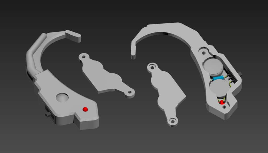
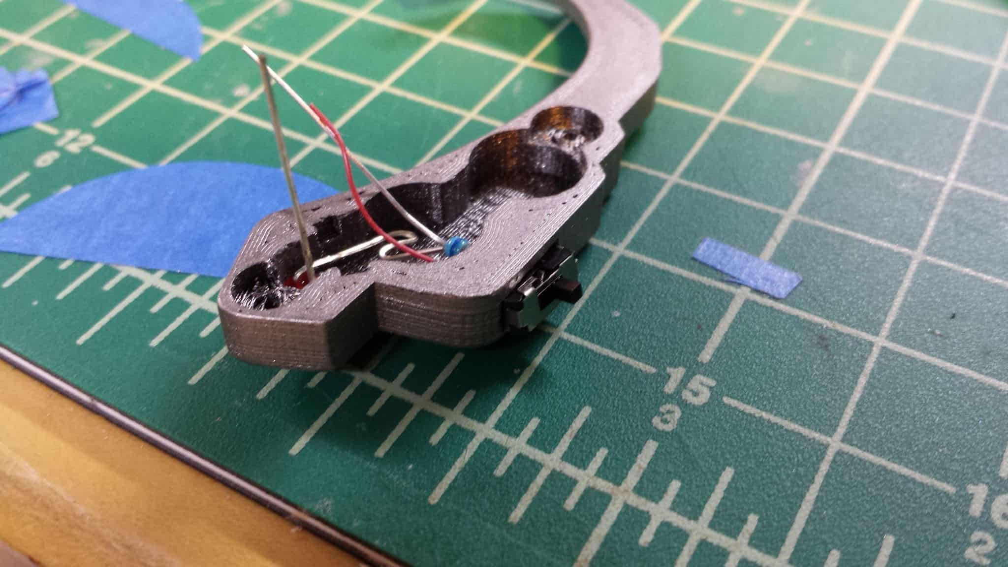
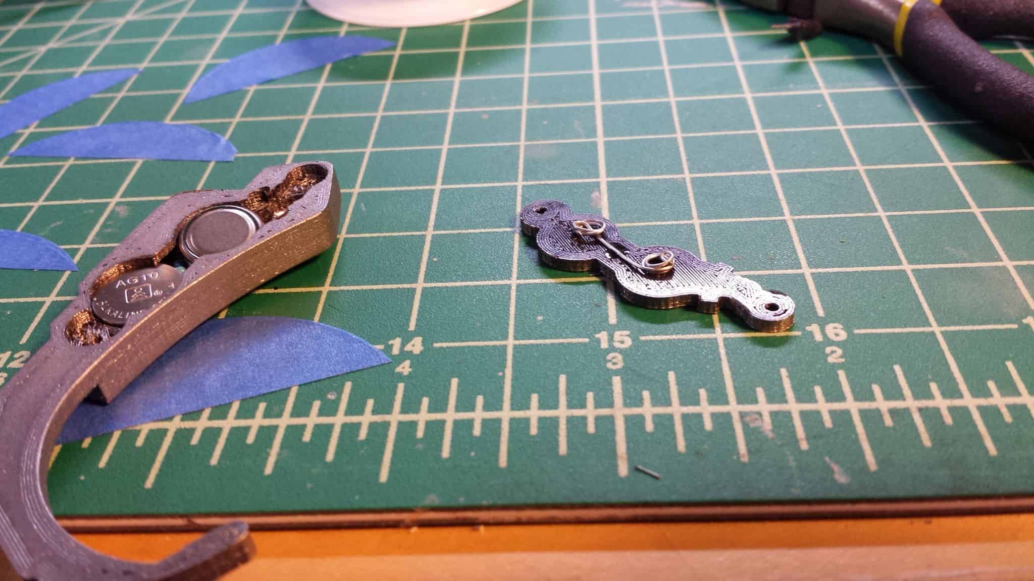
Insert your switch assembly into the appropriately sized hole on the back of the earpiece.
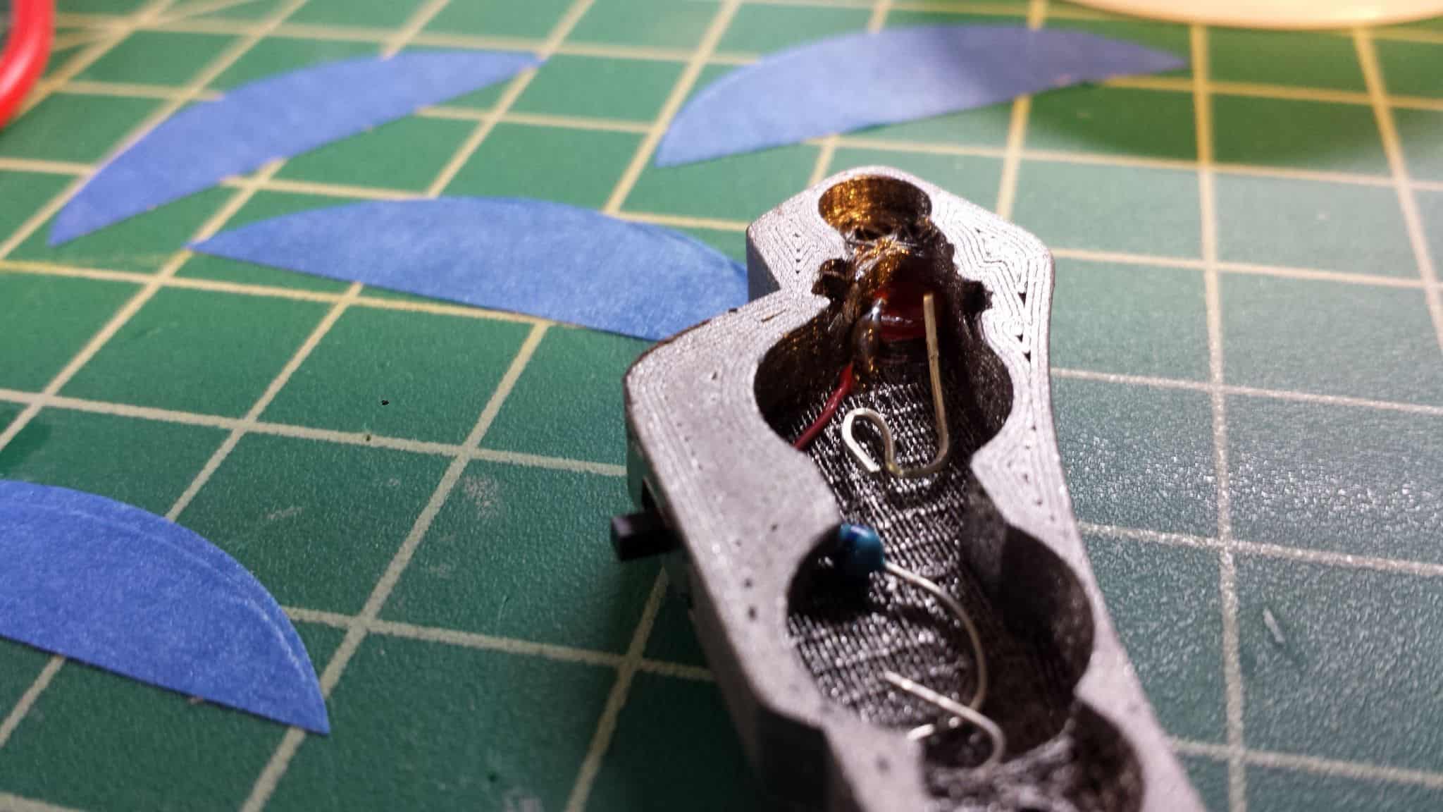
I did a poor job photographing it here (and, well, for this whole post), but what I’ve done is I’ve taken the longer remaining leg of the resistor and wound it up on itself inside theearpiece. This is a contact point for the second battery! The red wire coming from the switch was soldered to the other leg of the LED, and the excess lead was snipped from the LED after.
Taking a bit of spare wire, I coiled it on itself and glued it to the back plate in the middle to hold it in place. What we’re doing here is we’re making a bridge between the two coin cells so that we end up with the batteries in series, to give us a combined total of 3 Volts.
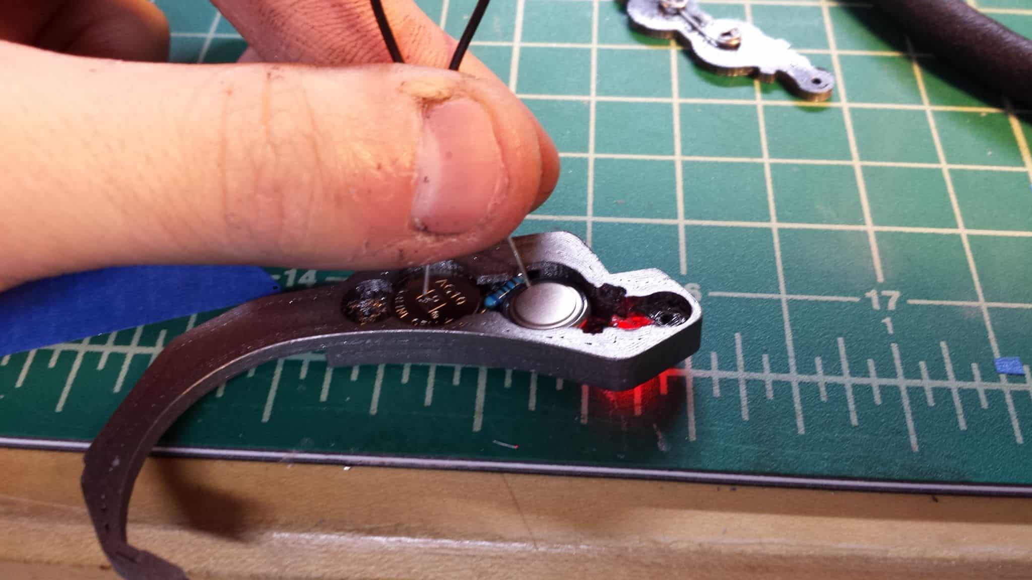
I’m holding a wire to both batteries in place here. You can see that once the batteries are joined together across their tops, the circuit is complete, and the LED glows. Make sure you have the switch in the on position! It’s just an easy way to test to make sure you haven’t bodged any of the connections.
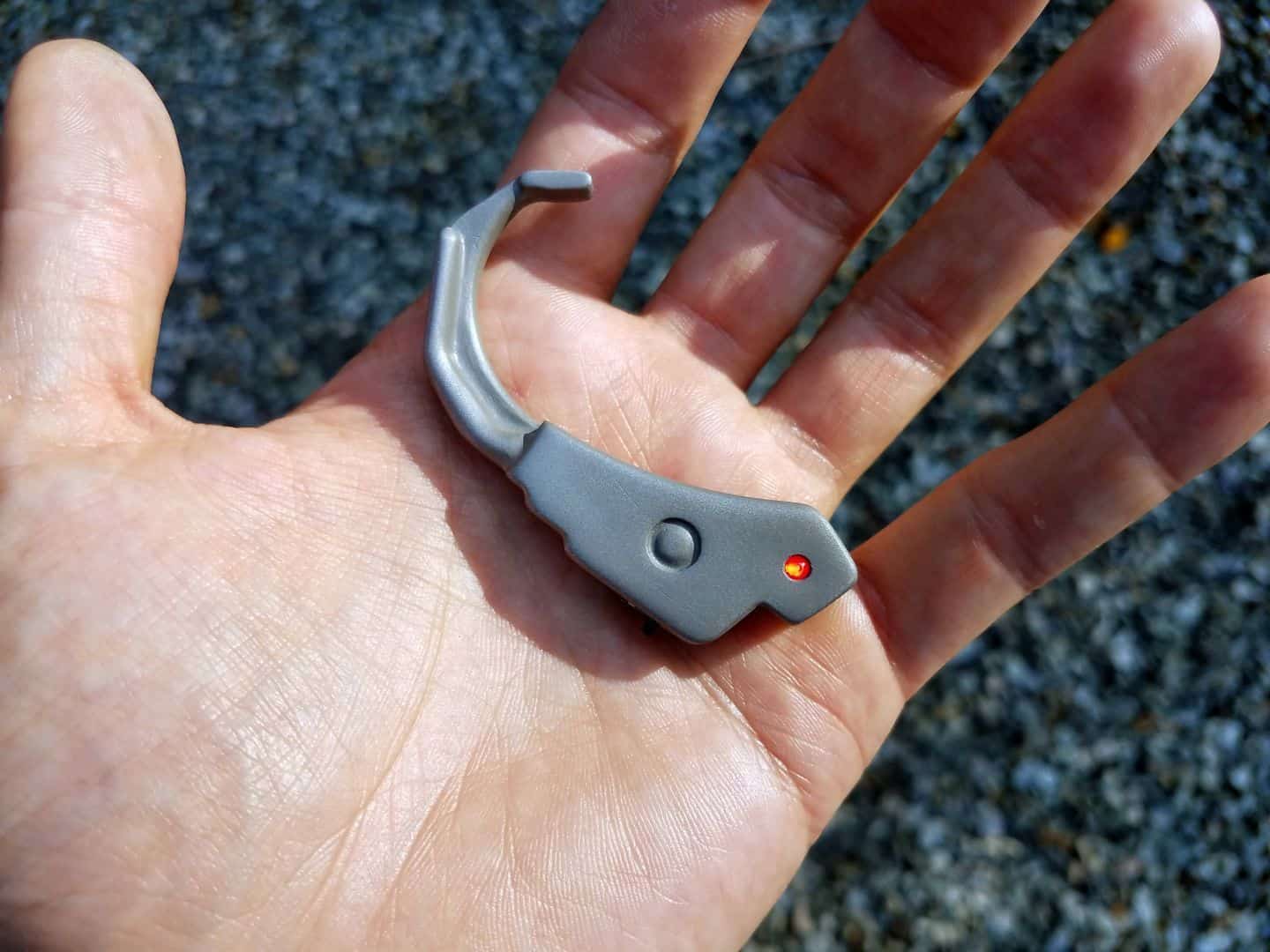
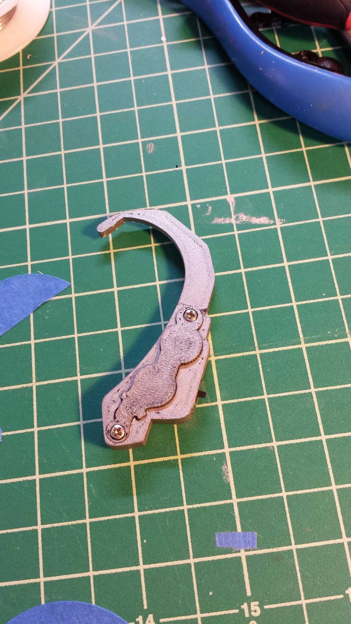
Screw the back on, and you’re… well, done.
I will say that I could probably thicken the entire earpiece by about half a millimeter to get the battery cover sitting as flush as possible. As-is, I overwound the wire on the back cover a tiny bit, and it pushed the back panel up away from the body a touch. No big deal, nobody ever really sees the back of this thing anyway.
