Giving thanks for Thanksgiving, at least for the time off it gives me.
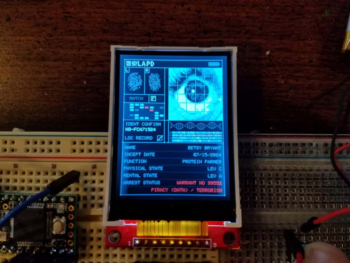
Profile pages are coded up and done now. I’ve made things easy for myself here by setting up a few profile ‘types’ in advance that I can change with a flag in the code.
//0 = K, 1 = DECKARD(YOUNG), 2 = CUSTOM HUMAN, 3 = CUSTOM REPLICANT, 4 = CUSTOM INDETERMINATE
#define userSelect 0
//0 = WALLACE CORP REPLICANT, 1 = TYRELL CORP REPLICANT. Only used if User is Replicant.
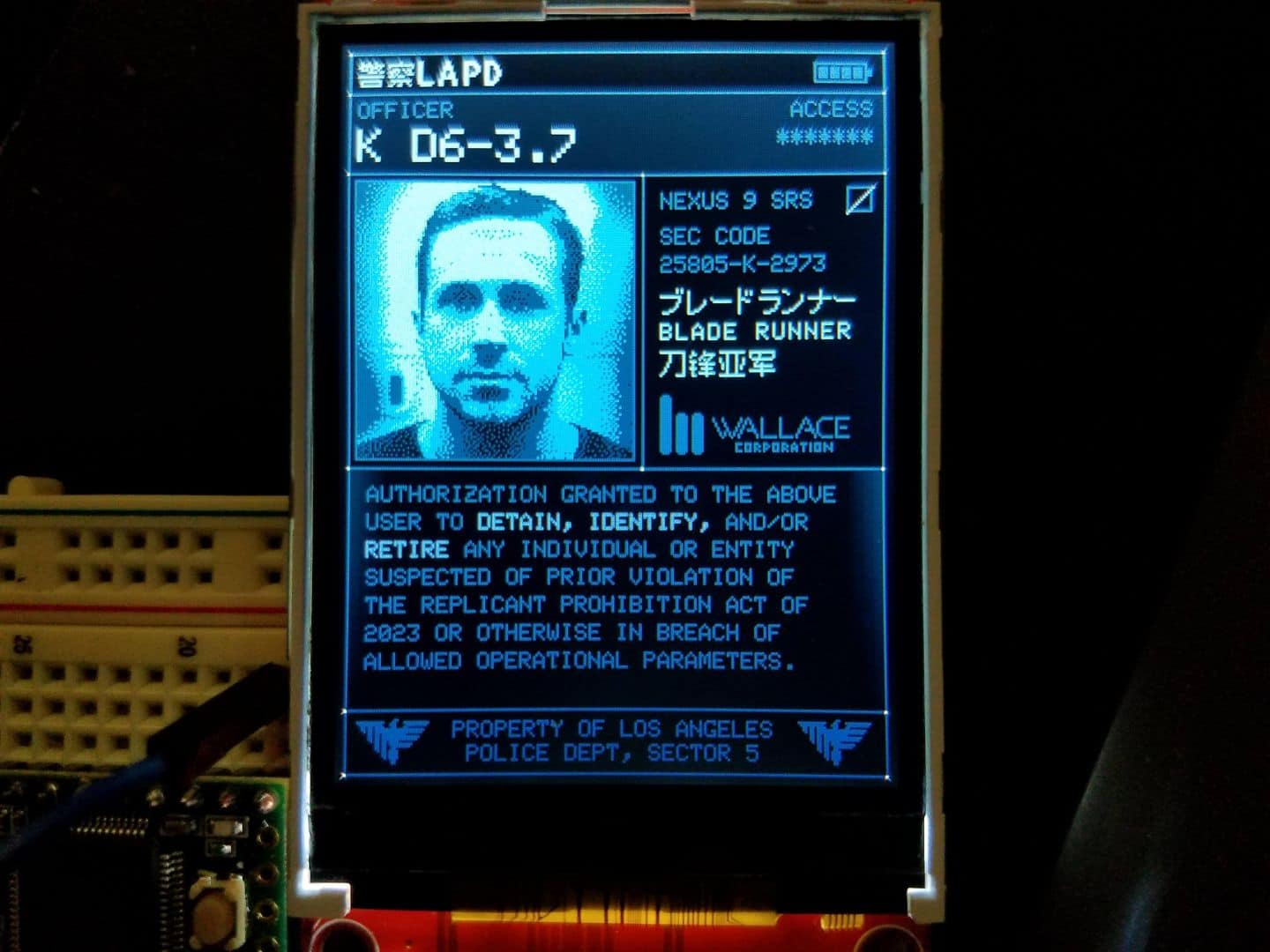
#define replicantType 0 By changing these two defined values, I can switch what shows on the profile page. A default unit that shows its operator as Officer K would have the userSelect flag set to 0 and the replicantType flag set to 0. For folks that want to have their own portable VK scanner customized, they can pick a profile that will display them as a Human, a Replicant, or Indeterminate. The “Indeterminate” flag is just one I thought would be fun, and use on Deckard’s own profile – instead of the Nexus Model or “Human”, it displays part of the word “Replicant”, writes garbage data over it, then writes the word “Human” after and leaves the checkbox next to that field unconfirmed.
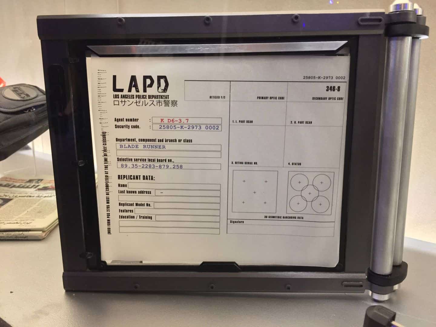
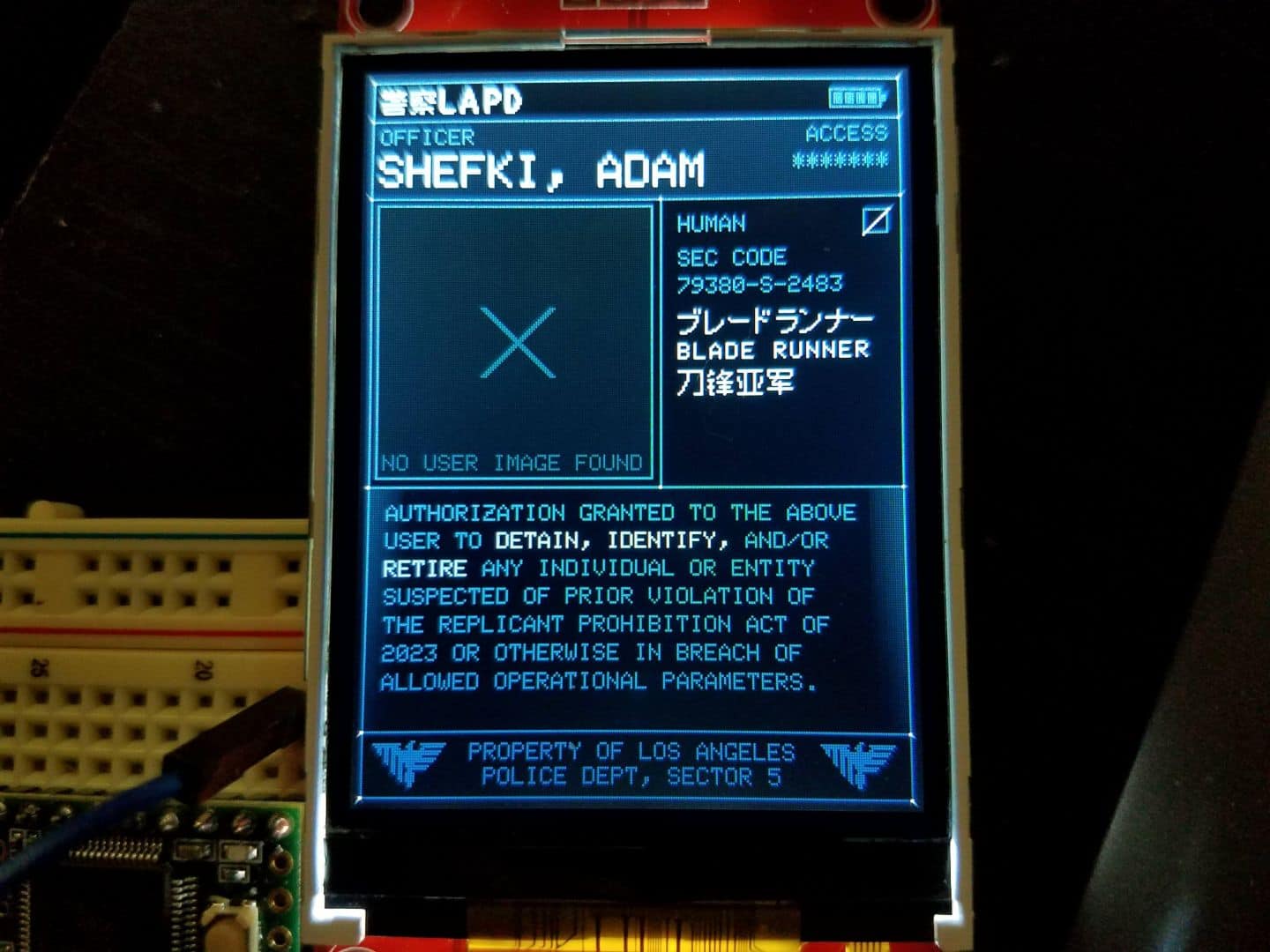
K has a movie-accurate security code, courtesy of one of the LAPD clipboard-esque display props:
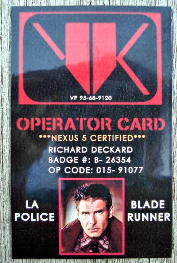
I made one up for Deckard using the info from this VK Operator Card, which itself references the screen-accurate badge number from the original Blade Runner movie.
Does it make sense in the 2049 setting? Absolutely not. Is it fun anyway? You bet.
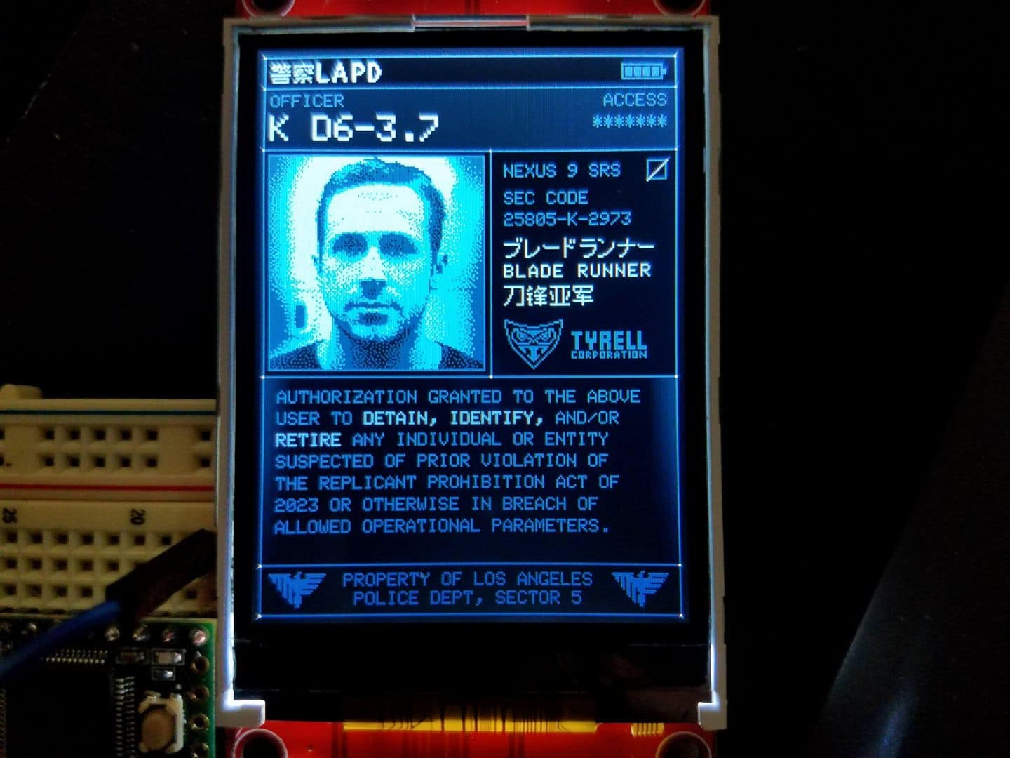
The “replicantType” flag simply lets me switch the logo that displays next to the profile of their manufacturer. Wallace is the default, but for the sake of it I added in a Tyrell option, which I will demonstrate using K’s profile here.
For “custom” profiles, it generates a unique security code per user based on their name. Specifically, it’ll take the user’s name, hash it into an integer value, then use that integer value in a randomSeed() function. After it does that, it generates a code in the format of #####-%-####, where the #s are randomly generated numbers from 0 through 9 and the % is the first letter of the user’s last name.
My favorite part about this is the fact that the code it generates, although random, will be consistently the same for the user every time because I’m using the user’s own name to seed the random number generator. This prevents the device from display a different security code for the same user on subsequent displays. It’s a little thing that nobody will ever notice or care about, but I’m happy that it is consistent.
The profiles are set up for me to easily change the images that display to suit the end user. If, for whatever reason, someone decided they wanted a custom profile but didn’t want their own picture on there, I could either set the images to be one of the pre-baked sets (K, Deckard), but I also went ahead and generated a “no user image found” readout just in case.
With all this sorted, I have to screw around a bit more with the animation options, which I will hopefully tinker with tomorrow.
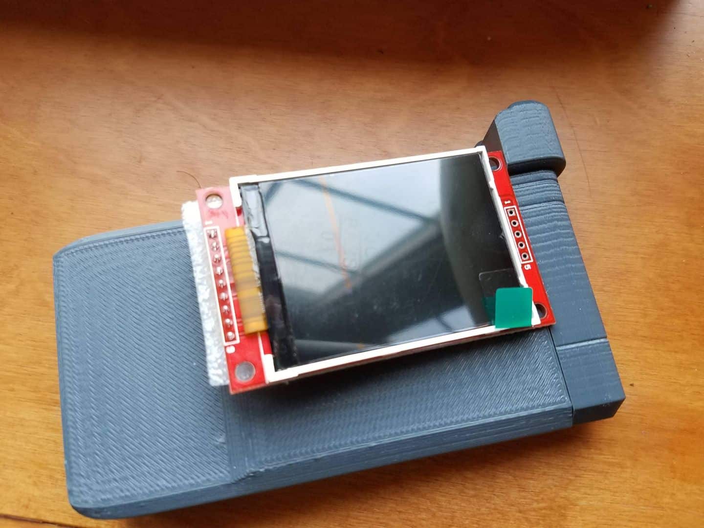
I also spent a bit of today working on a few other problems – namely, getting everything to fit inside the device in a smart and sensible way. As I mentioned in one of my prior posts, the ILI9341 TFT displays come in a surprising variety of sizes: 2.2″, 2.4″, and a whopping 2.8″. I have been working with the 2.2″ display thus far out of a concern for sizing, but have just noticed that this creates a tiny bit of an issue.
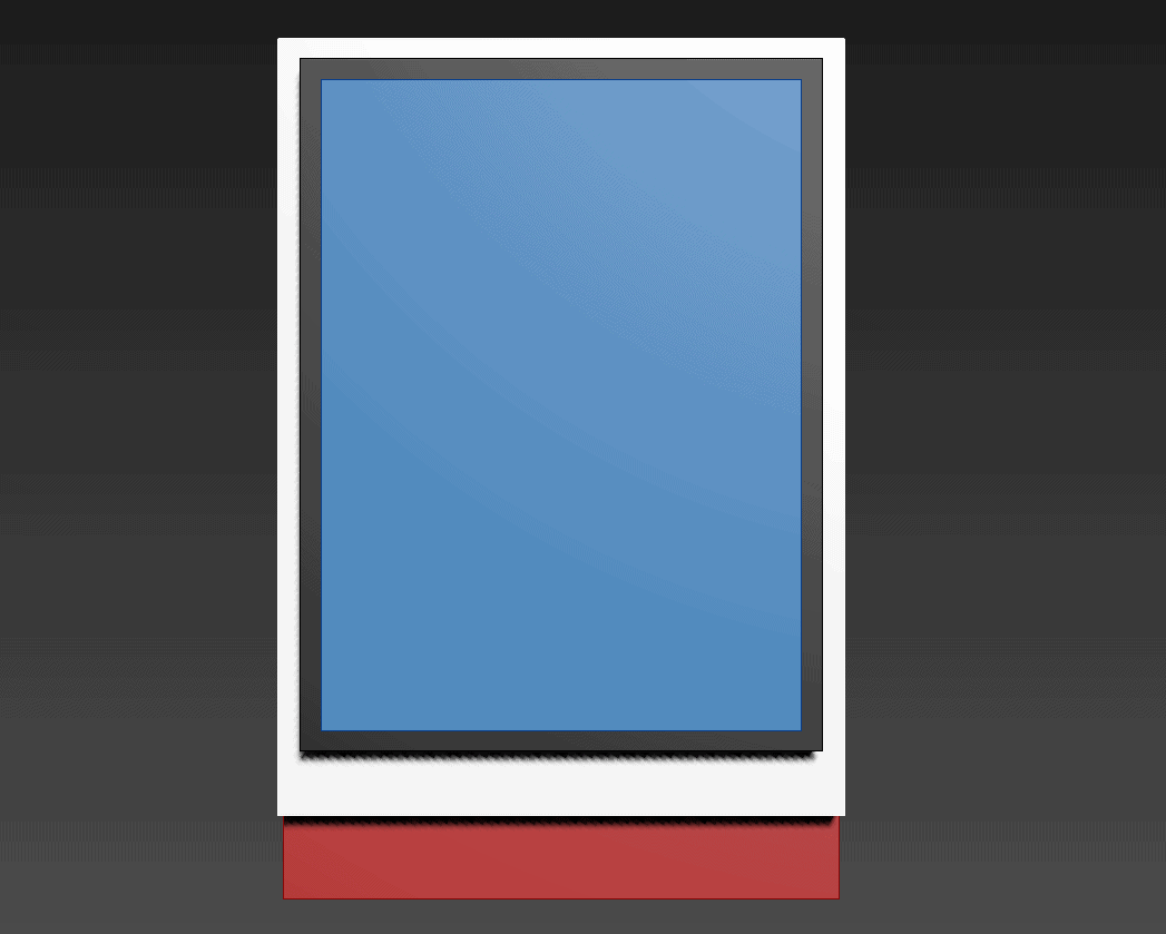
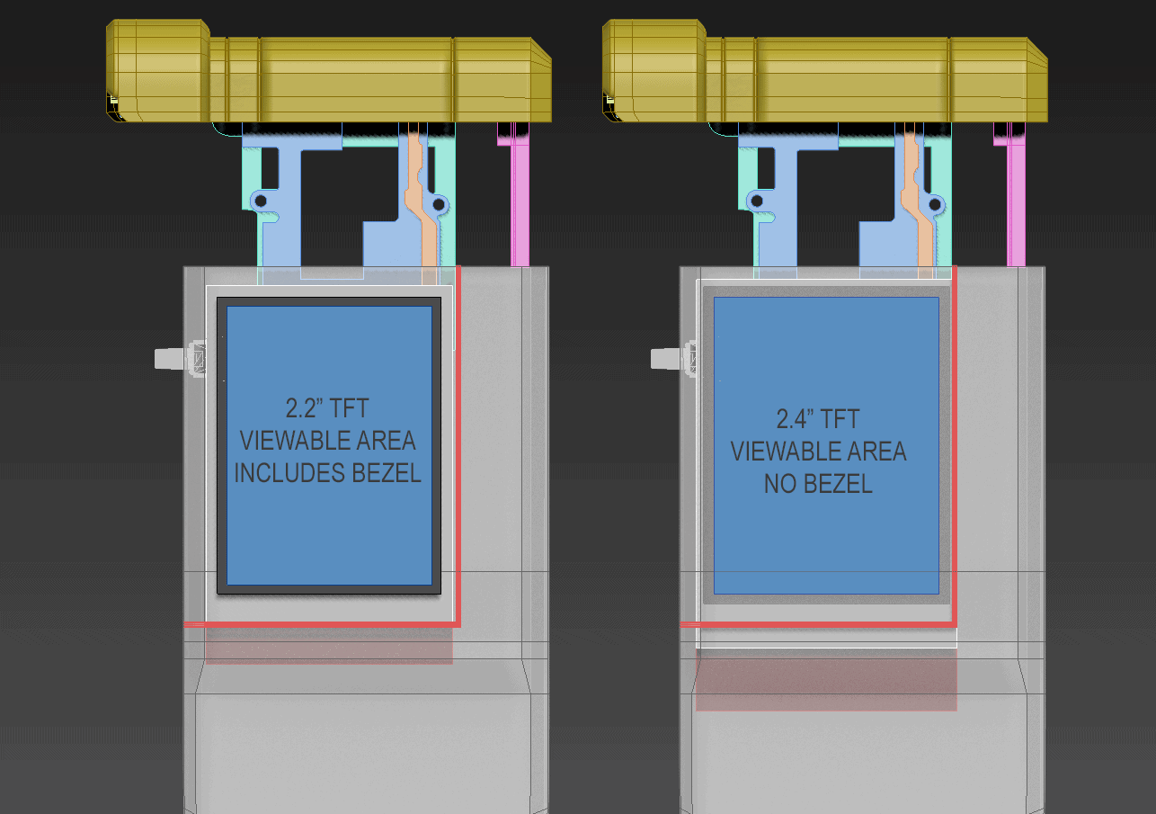
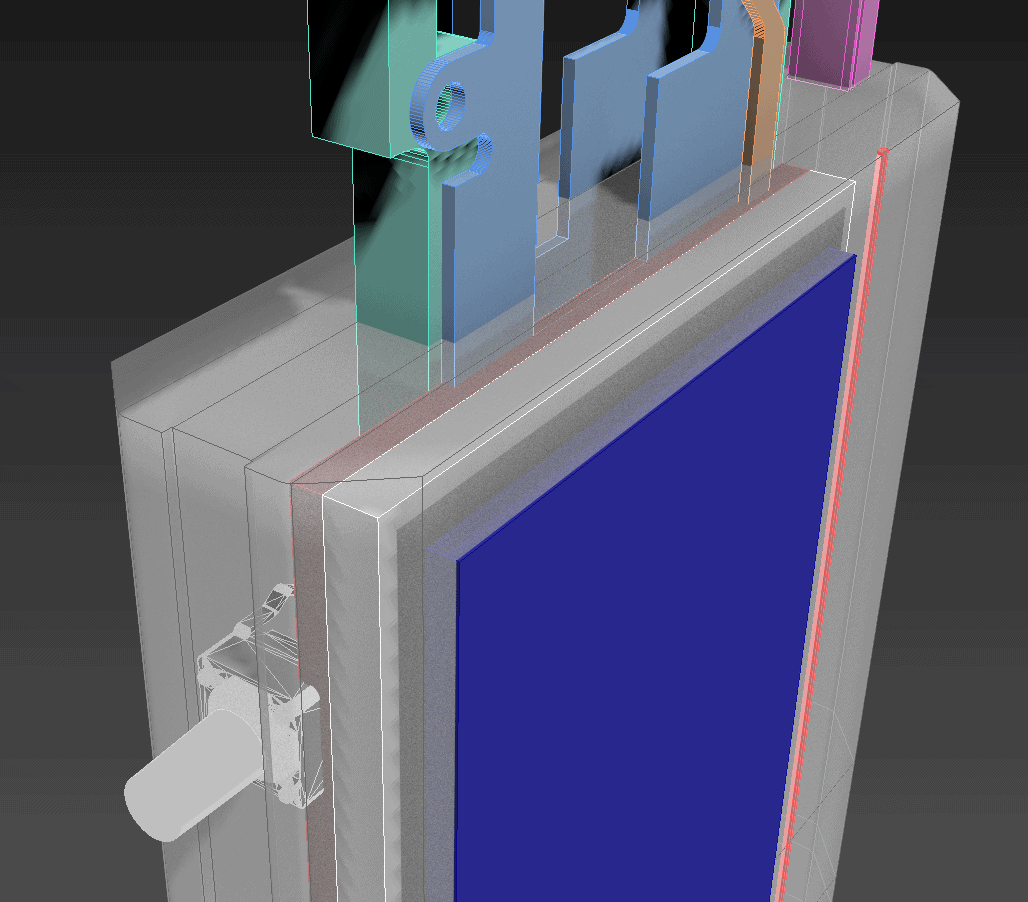
The screen has a viewable area indicated by the blue rectangle. Around it, there is a black bezel where no pixels can be drawn. Around that is a white plastic clip that holds the screen in place. These are not particularly large – the black bezel is about 1.5mm wide, and the white border about the same. My plan from the outset was to simply cover the bezel section with the VK enclosure, and have only the viewable area with the graphics show. However, once we put the 2.2″ screen into the device, we start to see that if I want the display to be close to the screen-accurate size, I can’t cover up the bezel. This creates a bit of a black border around the screen that I’m not sure I’m thrilled with.
It’d work, though, no question about that.
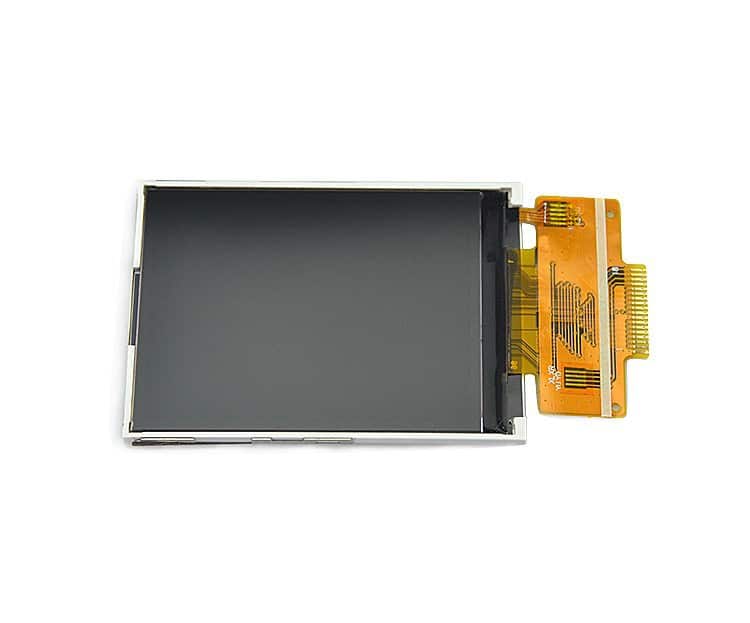
Still, I bought some of those 2.4″ displays to play with, so I went ahead and opened one up. From a bit of quick review, it actually looks like these would be able to fill the space without the bezel showing, which was my original intention.
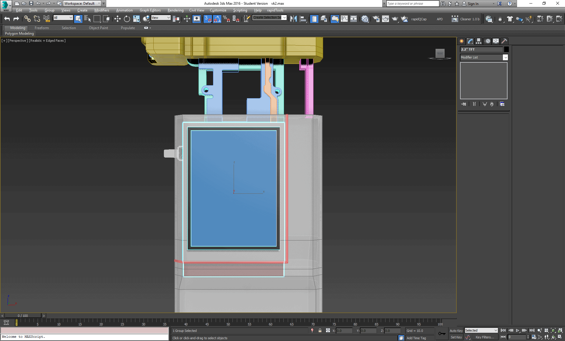
The downside to this arrangement is that the printed circuit board behind the screen is also a bit wider, which then starts intersecting with the switch I was going to put on the side edge of the device in a way I’m not thrilled with. It also somewhat gets in the way of the rails, as you can see in the picture here.
Both of these are actually totally solvable problems, fortunately. There is nothing on the PCB of any consequence above about halfway up the board. Given its design, you could get a dremel with a cutting wheel and cut everything to the left of the dotted blue line away and still have a totally functional device.
Now, if this was a one-off thing, that’s probably exactly what I’d do. However, I’ve been thinking about making these for sale. I do not think I could bring myself to try and carefully cut a hundred PCBs in that fashion. I also think I’d probably fail on a good number of my attempts.
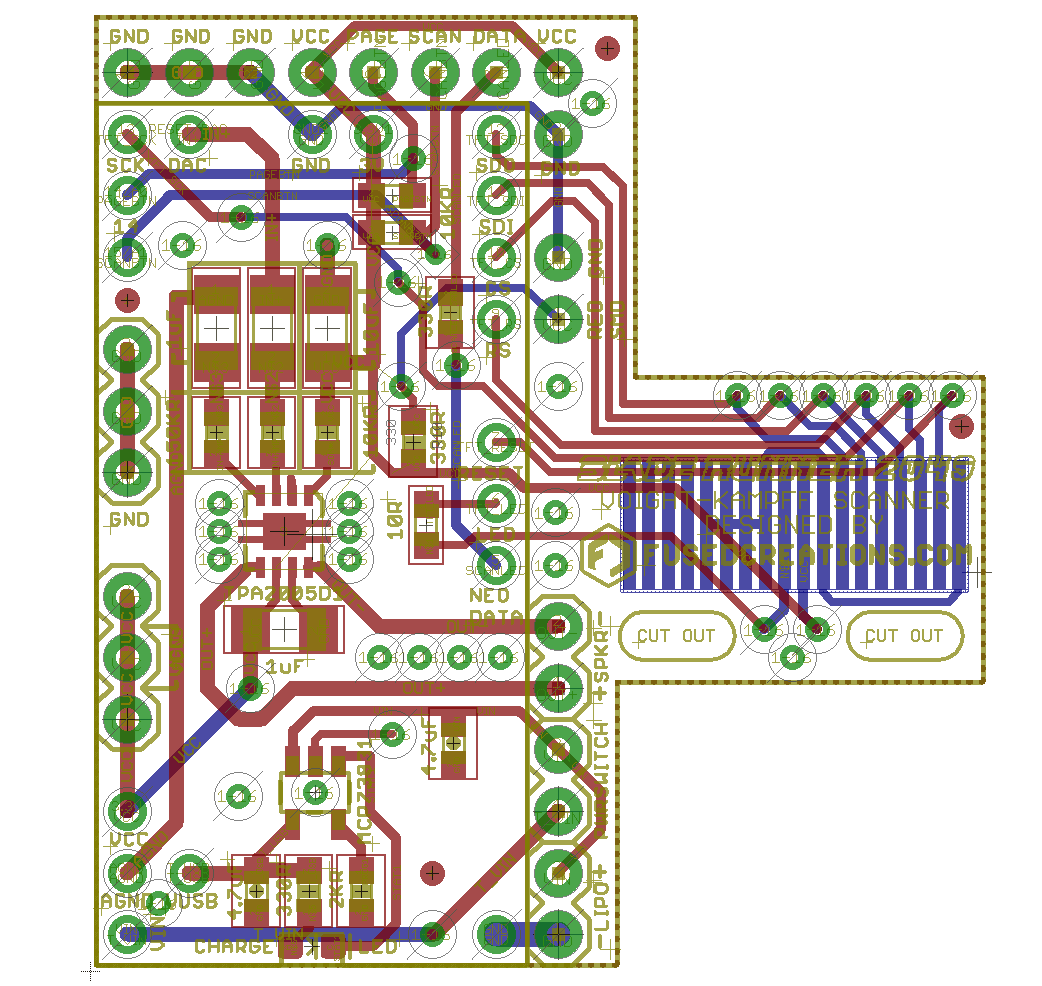
I realized that it’s possible to actually buy the ILI9341 displays without a PCB at all – just the display and a ribbon cable.
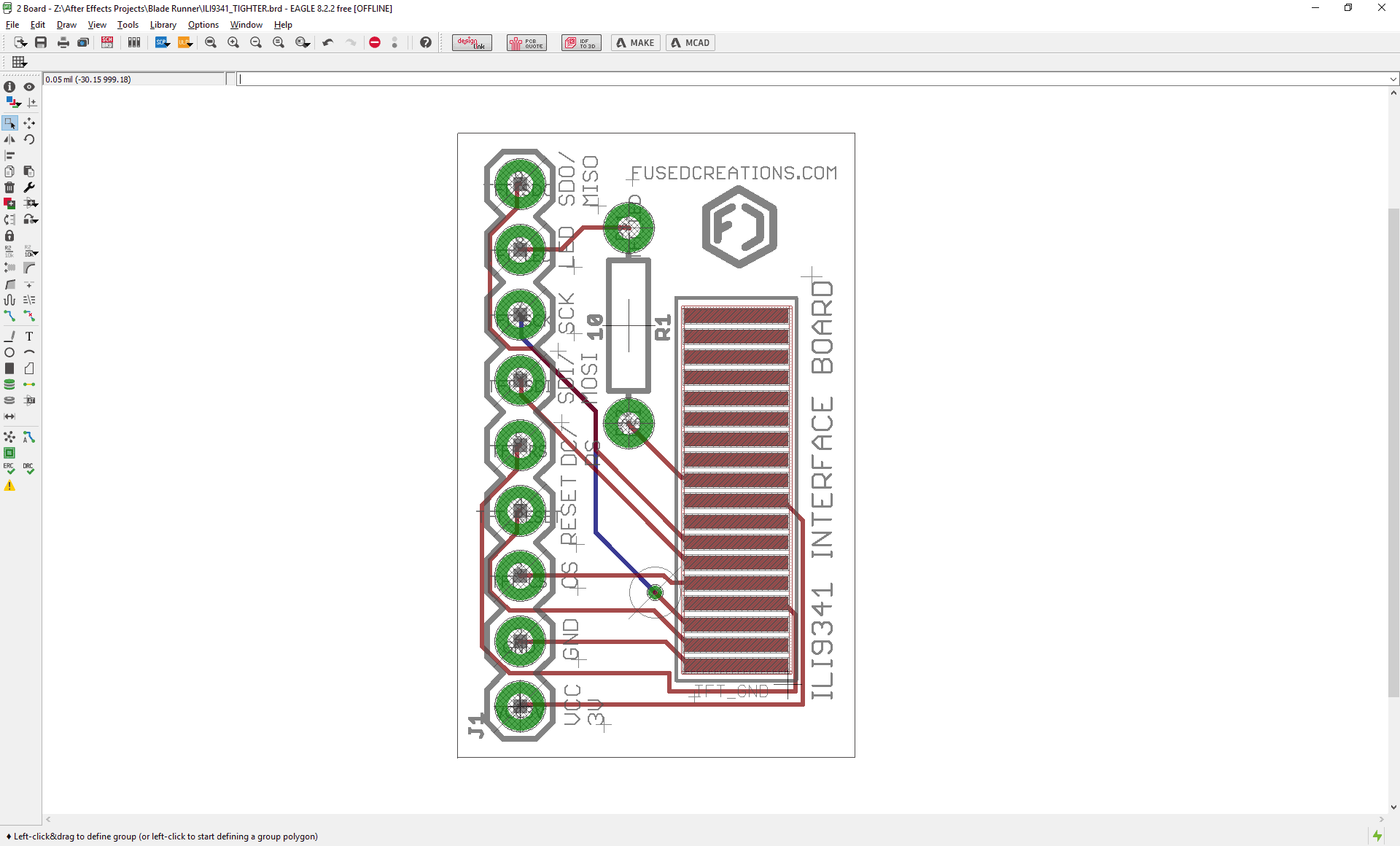
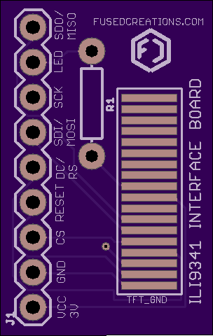
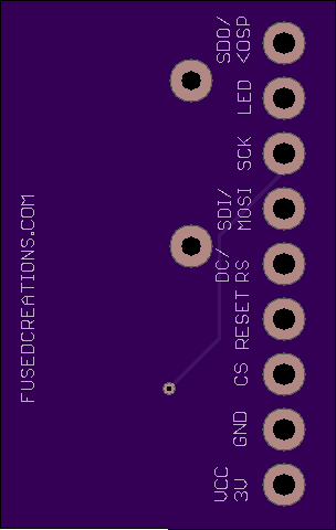
The ribbon cable is probably the only awful part of this, if only because it can be very tricky to solder those correctly. You still can’t get away from needing a PCB to do these things – it’s impossible to try soldering wires to the ribbon like that. In order to come up with a solution, I spent my evening learning EAGLE, which is an electronic design software that facilitates schematic and PCB layout. After a good amount of swearing and some watching of Youtube tutorial videos, I think I’ve gotten this to a point that works.
For what we’re doing with the ILI9341 displays, I really only need access to 9 traces on that ribbon. This design is effectively a breakout board that spreads those traces out into proper human-workable pin headers that I can solder wires to. I also added a spot for a resistor inline with the TFT screen backlight so that I could make sure it had some degree of protection. I could have set it up for a surface-mount resistor – something like a 1206-sized piece – but I figured the whole point of this board was to make my soldering work easier, and I find the through-hole resistors to be dirt simple. I did some automated sanity checks in EAGLE to make sure I wasn’t screwing anything up or leaving anything important disconnected, and I’ve placed an order for a couple of these boards with OSH Park. Will they work? I have no idea. If they do, they will be a super nice solution to some of the size constraint issues I was working with, and they will also make the devices go together a lot easier and with a lot less stress. They’d also actually end up making the electronics cheaper – buying the ILI9341 display without a PCB is a fair bit less expensive, and these cost very little to have manufactured to replace the missing PCB components.
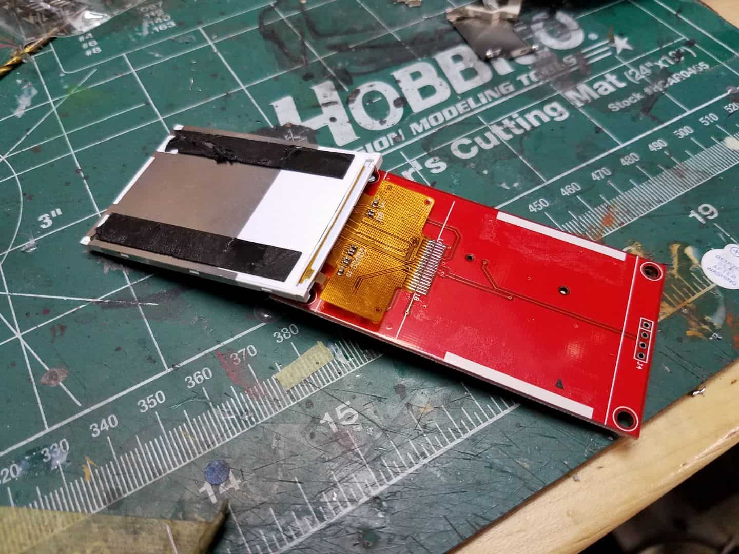
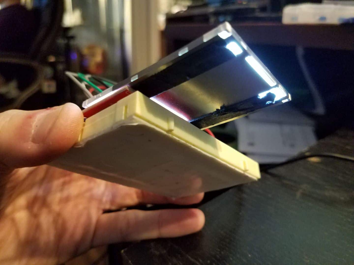
Ordering some custom PCBs is all well and good (and I have placed that order), but the truth is I need to be able to get on with the design. The dremel-cutting-wheel approach needed to be tried so I could keep things moving. Fortunately, I think I overestimated just how hard it would be to actually work with the existing red PCBs on the 2.4″ screens. I had one screen to spare, so I went ahead and did some surgery on it. The TFT display is stuck down to the PCB with some thin double-sided tape. If you aim a hair dryer (not a heat gun, we don’t need that much temp) at the display, you can start to soften the tape up enough to slip a long xacto knife or similar blade behind the screen, between it and the PCB. A bit of patience and gentle persuasion lets you pop the whole TFT assembly right off the board.
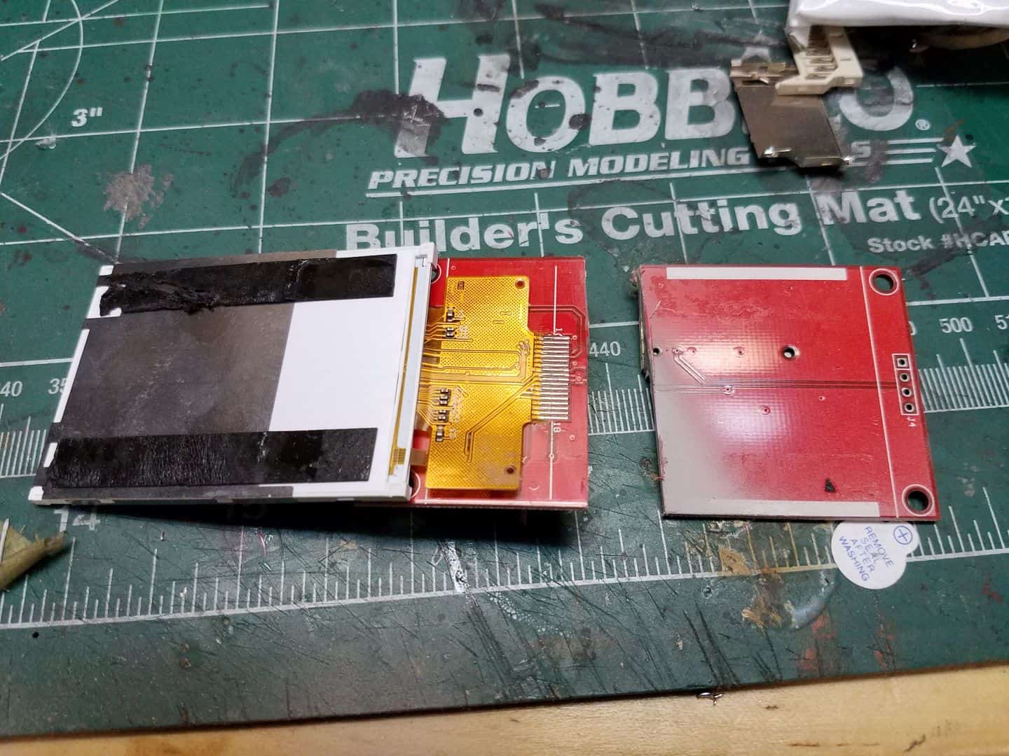
Getting the screen detached from the board means it’s a lot easier to just chop the bits of the PCB that are no longer required off completely, and also means that you can see both sides of the board to make sure you’re not about to cut something vital.
I held my breath and went at it with a cutting wheel on a rotary tool. Got a little close to one of those traces, but not enough to break anything.
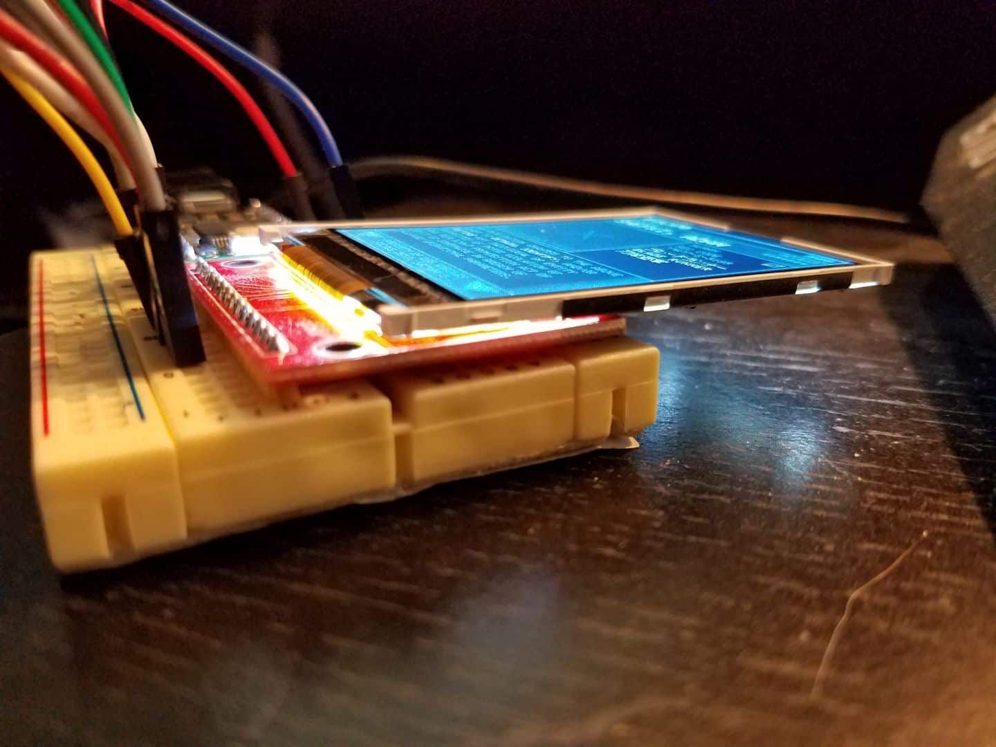
Still works! If I had to do that to a hundred of these things, I probably could. I’ll still play with the custom PCB option as it may also give me a place to mount other needed bits for the internals. We’ll see where the design takes me!