A few weeks ago I sent Doug Harlocker, the props master for Blade Runner 2049, a message asking for information about this prop. I never got a response. That’s totally fine, and what I expected – the man’s an important and busy dude. However, it is now my powerful and compelling goal to make Doug Harlocker rue the day he ignored my e-mail. I plan on accomplishing this by one-upping his screen-used prop, making something even cooler than what was actually used in the film. You hear me, Doug? You hear me!? You will rue the day!* This post is going to be focused on precisely how I plan on accomplishing that. I did say I was going to be exhaustively thorough about this, so it’s time for me to hold up my end of the deal. This is going to be focused on the nitty-gritty technical details.
*I am totally kidding about the above and have nothing for the deepest respect for Mr. Harlocker, whose work (and the work of his team) is exceptional. Just playing, yo.
(please notice me)
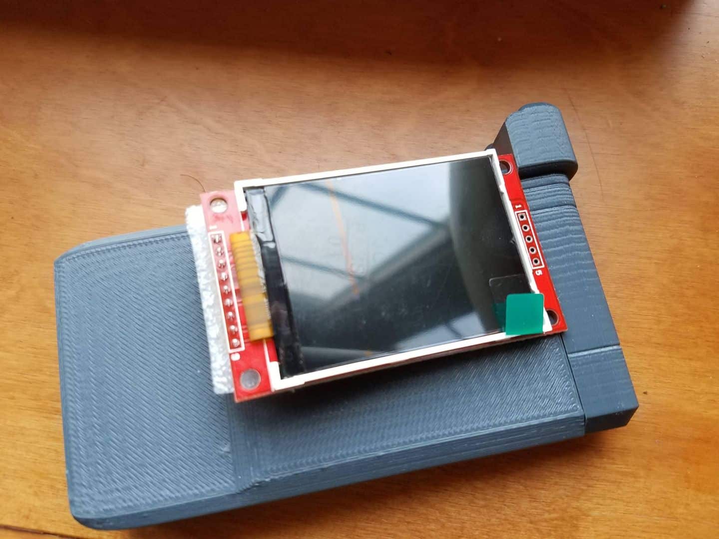
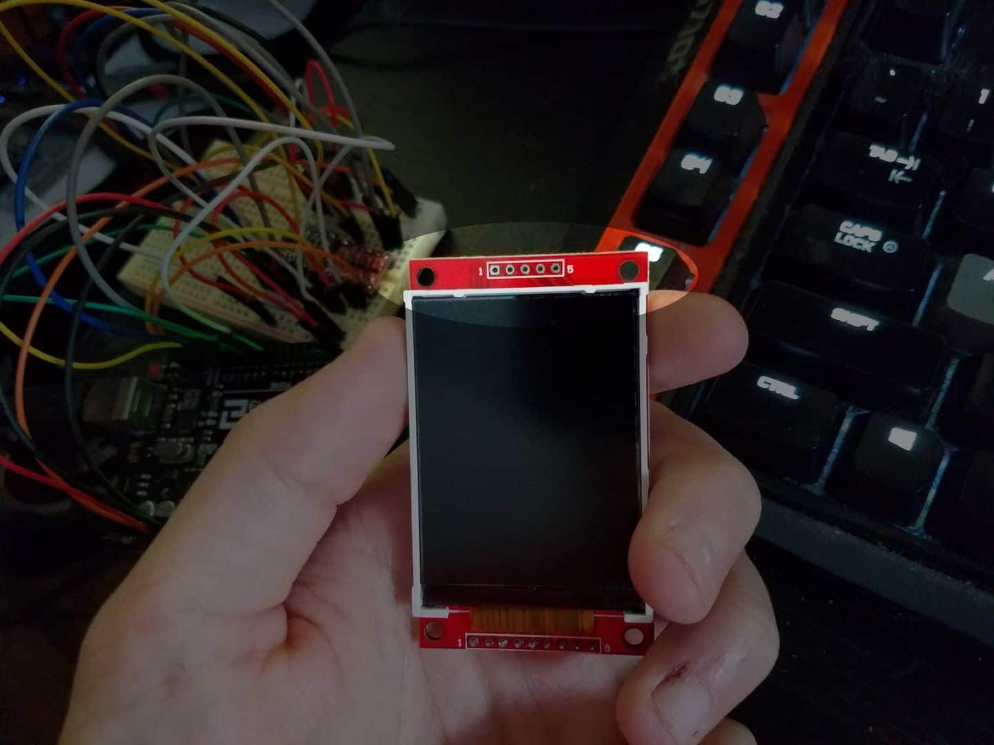
When I watched the video of Adam Savage getting a hands-on with the screen-used Voight-Kampff scanner, I noticed that one of the devices had a green screen, presumably for the inclusion of CGI in post. From what I saw of the film, the scanner never actually has a scene where it displays anything, so I suspect they nixed the idea in favor of the bigger display in Officer K’s car. Since the start of this project, I had been assuming that I’d be making a ‘dummy’ screen in my device – an edge-lit piece of laser-cut acrylic that would flash at the right times, but otherwise not display anything. Still, I wanted to experiment a little bit, so I bought a cheap 1.8″ TFT LCD Display to work with. I picked this module up specifically because of the way it was laid out; most displays have a printed circuit board (PCB) that extends past the display boundaries, as this one does. If I tried to build it into the spot I needed on the portable VK, the red top end of the PCB would stick out when the camera unit was popped open, which would ruin the entire look the device. However, the way the pins are laid out on this board is particularly handy – that top row of solder pads is only for interfacing with the SD card.
This first screen uses the ST7735 display, and there are plenty of arduino libraries out there that provide support for them, including one from Adafruit. It didn’t take long for me to figure out how to hook everything up to bring the unit to life, which started opening up a world of possibilities for me:
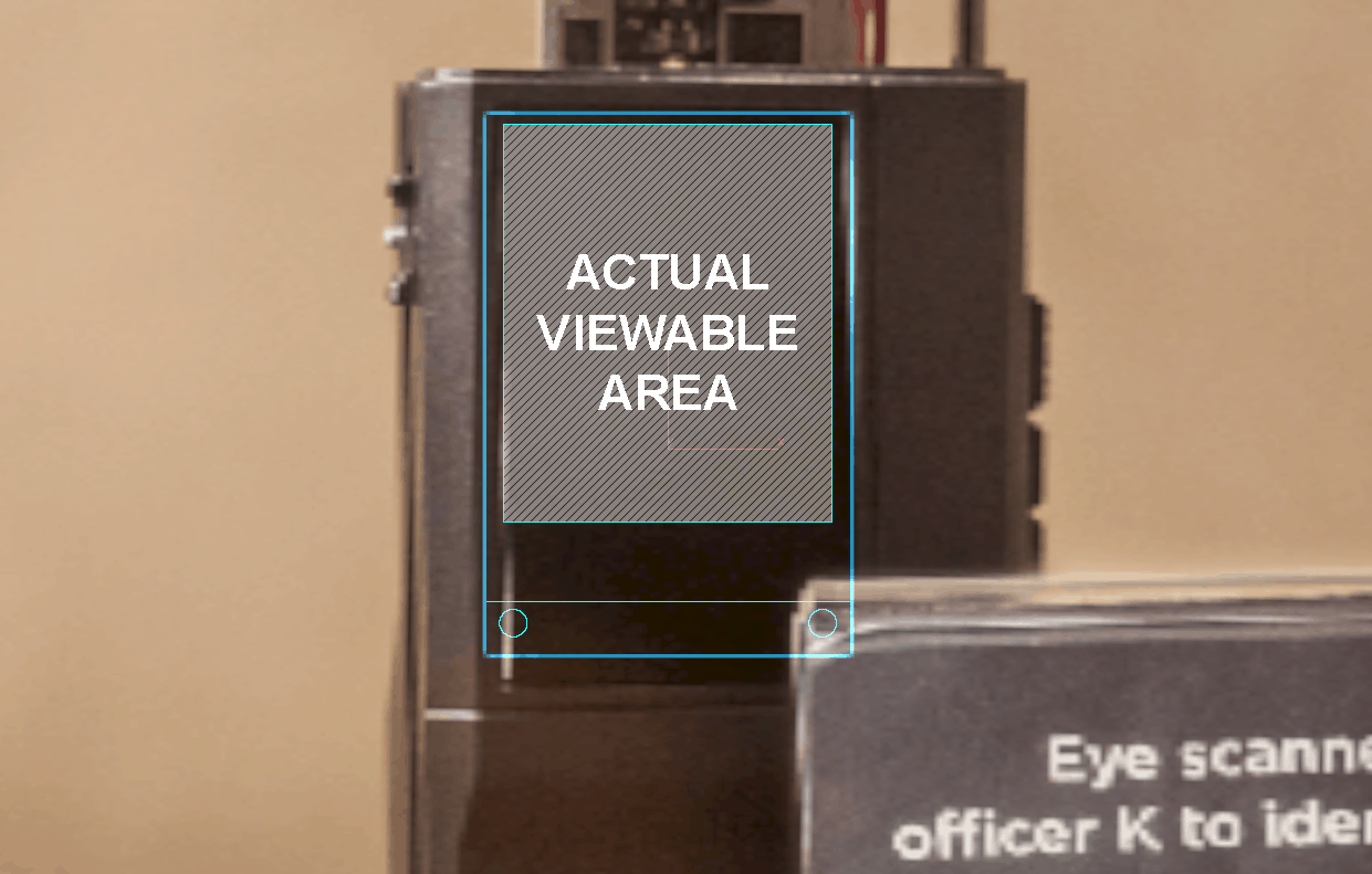
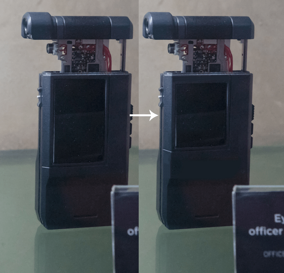
Now, this left me with a bit of a conundrum. This TFT display was a decent width to be a substitute for the device, but it is not as tall. I put together a quick model for scale comparison of the display I’ve been toying with and laid it over one of my to-scale reference images. I started grumbling about the sizing issue, and wondered if I could adjust the design of the device to accommodate the TFT better. I figured I could cheat it a little bit by bringing the top of the screen down and the bottom of the screen up, but it starts to change the overall appearance of the device. I photoshopped a quick example of what I’m talking about.
I was not happy with this compromise. It would have worked, but it also would have made the device look pretty stupid. I started having that age-old internal debate about whether or not the screen gimmick was worth the trouble. As I mentioned, my initial idea was just to edge-light a piece of smoked acrylic with white SMD LEDs. However, soldering SMD LEDs is a total pain in the backside, and I’d have to do 2 or 3 along the bottom edge to get the sort of lighting I’m looking for. The screens represent a more ‘drop in’ solution in that regard, and even have independent backlight controls, which means I can easily flash the display with nothing on it or strobe it during scanning in the same way that I would with the white LEDs. I guess there’s an argument to be made that screen accuracy would dictate that a working screen would actually detract from the simulacrum of the prop, but… no, come on, when have I ever taken the reasonable course with these things?
I knew there had to be a better option, and set about digging through the internet at large for alternative parts. Then, like magic, I think I found it: A 2.2″ display off Amazon with the same PCB layout, just scaled up. Bingo!
These newer, bigger screens not only fit the space comfortably but they have a substantially higher resolution – 240×320, nearly four times the pixel density of the initial display I had been playing with. I’m hyped about that because it starts to open the door for me to create higher resolution imagery that better portrays what I have in mind for the device. This device runs off a different library than the first – it is an ILI9341 display. Again, there are tons of compatible libraries out there, including ones by Adafruit.
Now… now we get into process. We’re going to talk about the coding of the display itself, the challenges involved, and how I might be able to overcome them.
DRAW SPEED
As I mentioned, there are plenty of compatible libraries that can turn the screen on and display graphics without issues, but they tended to be sloooow. I discovered one bottleneck was the fact that my arduino was in what’s called “Software SPI” mode; SPI stands for Serial Peripheral Interface, and is sort of the language the Arduino uses to “talk” to other devices. “Software SPI” is also known as “bit banging”, which is a great name for anything. The best summary I can give right now is that it involves making the microcontroller in the arduino do a lot of the heavy lifting before it sends the data to the screen. This is nice for compatibility, as you can have the microcontroller handle things like timing, but it also slows everything right the hell down, as you end up using CPU cycles on the microcontroller that could be better directed towards other functions. On something like a PC CPU, it’d hardly matter, because we’re talking about zillions of calculations per cycle; on a tiny little Arduino, it’s a visible dip in performance.
Fortunately, there is a “Hardware SPI” implementation for almost all of these setups, which seems to basically involve trusting the display to figure out a less-sanitized and prepared input. This runs three to five times faster from what I’ve seen – it’s the difference between watching a screen slowly fill with a color, and doing it instantly. It took some figuring (and some soliciting help on the official Arduino forums) but I’ve got the setup figured out and running smoothly now. Everything works, and nice and fast! Hooray! On to the next challenge…
TAILORING THE SCREEN
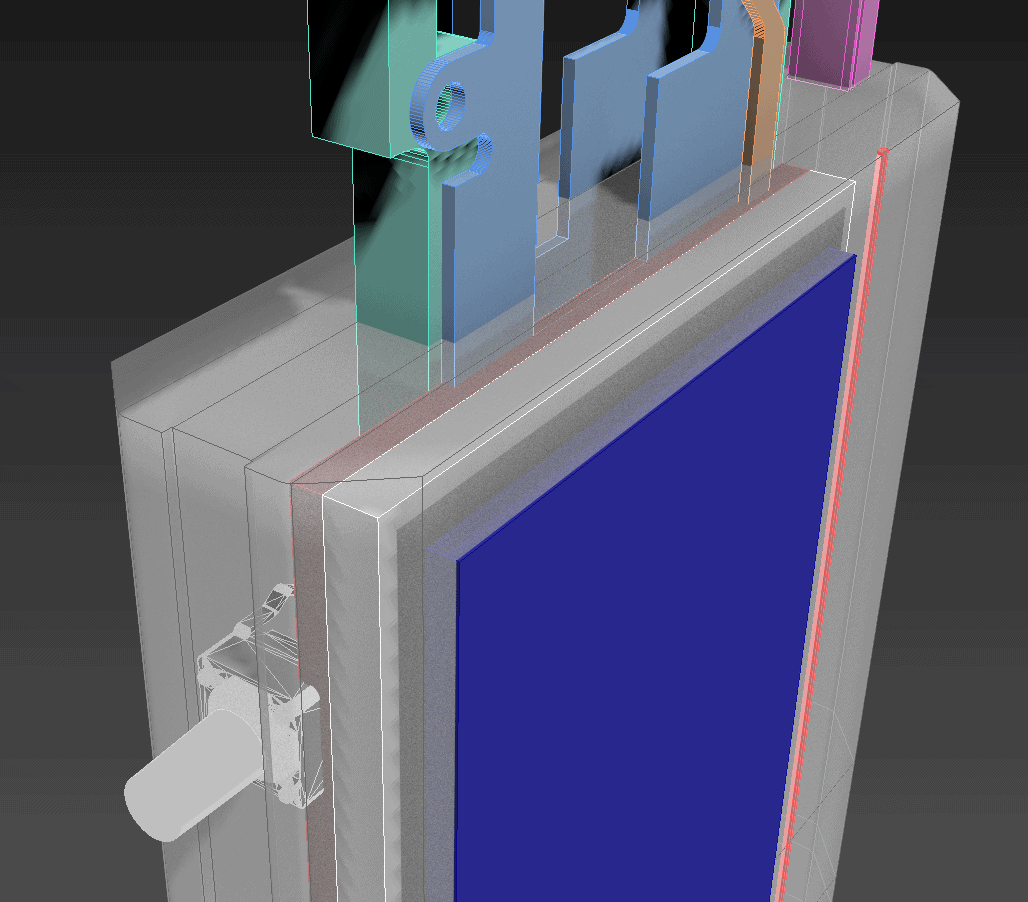
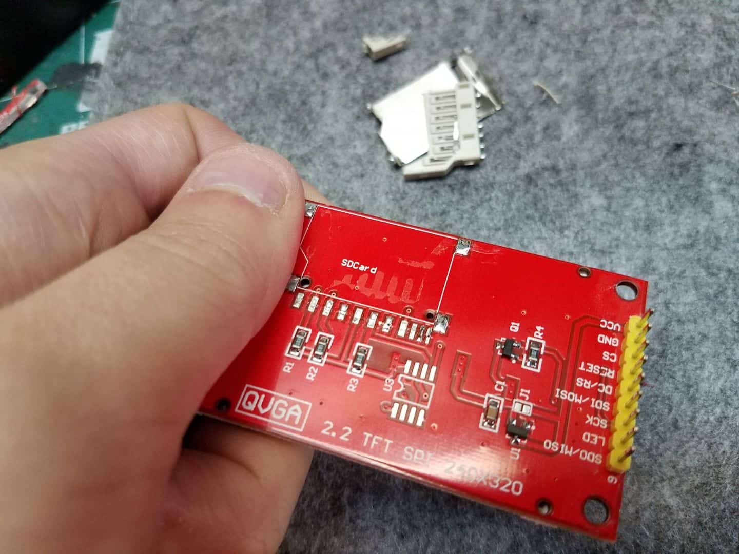
There are design limitations posed by the Voight-Kampff device itself. In order to use the SD card functions on this board, you have to wire to the appropriate pins. The “appropriate pins” in this case are at the top of the board. If you look at the design of the VK, you’ll see that the screen itself is pretty close to the top of the ‘base’ unit – almost flush along the top, really – which means that this red circuit board would be sticking out once the pop-out component extended. That’s no good. That’d ruin the look of the prop.
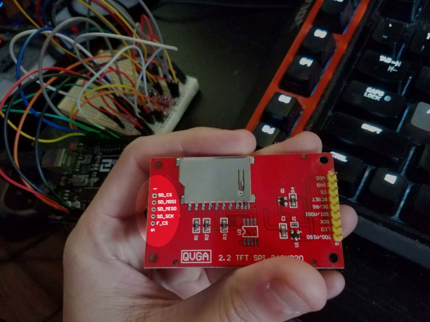
Fortunately, if we take a look at the back of the board, the SD card reading elements are totally isolated from the rest of the board.
Another thing to consider is that the SD card reader itself is actually a pretty big component. The screen itself is surprisingly thin, but the SD Card enclosure is nearly the width of the rest of the unit again!
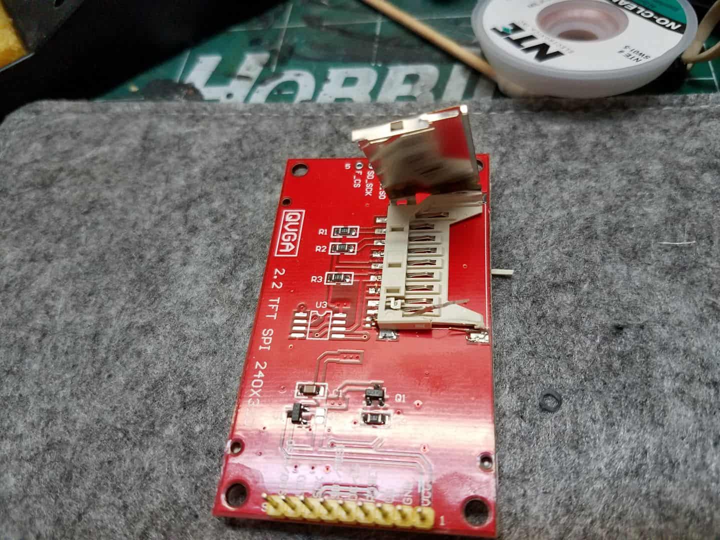
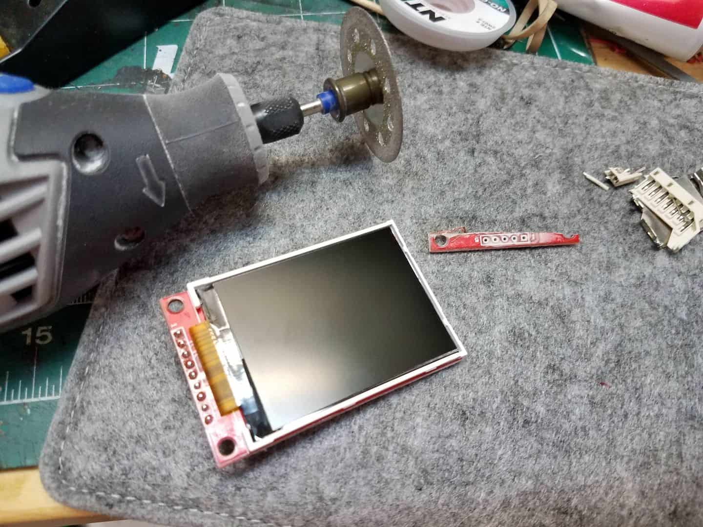
In light of all of the above, it’s clear: The SD card stuff has to go. Thanks to the way the board is designed, this is totally doable! Step one is to take a soldering iron and some solder wick/ solder braid to start desoldering the SD card holder. You heat the iron up and press the solder wick between the hot tip of the iron and the pad you are attempting to remove the solder from. The solder softens and flows into the copper weave of the wick, which you can then pick up. 90% of the solder holding a joint will come with the braid when you do that. Do that to each of the pads holding the SD card connection down and you can start to pry it up and off the board. The whole thing ultimately came off pretty cleanly.
The top row of the PCB had to be removed, which was easily done with a dremel and a cutting wheel.
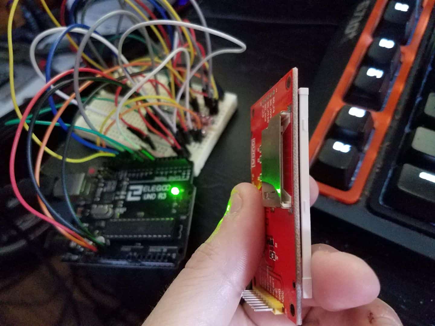
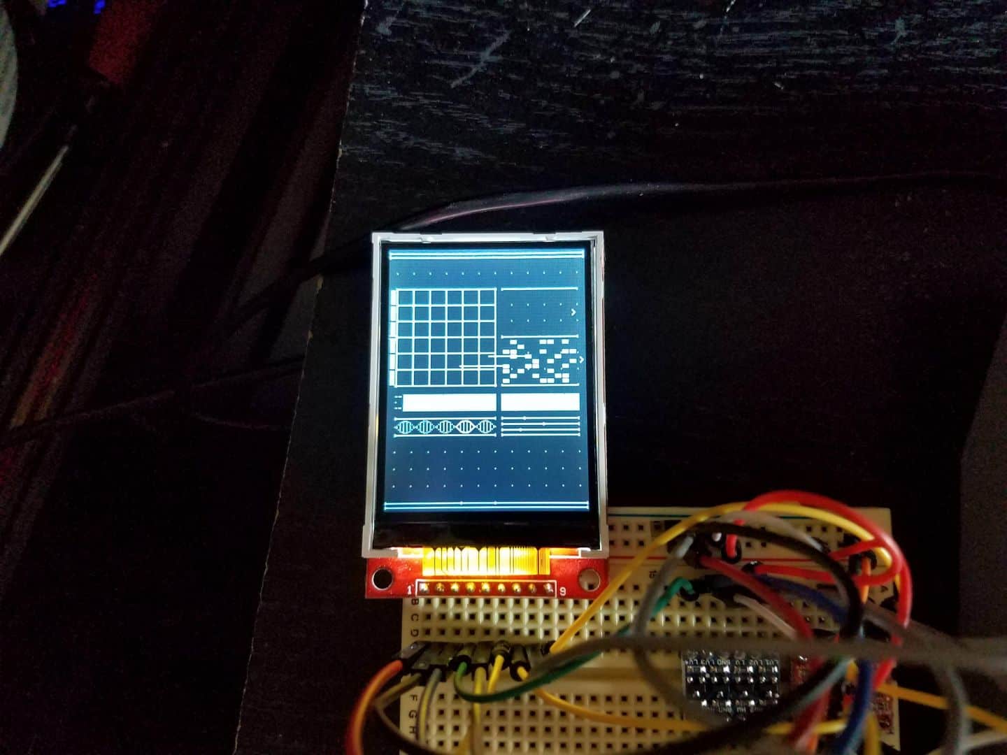
After all that, the moment of truth is whether or not the screen still works. I’m happy to report…
Yep, still good! On to…
THE MEMORY LIMITS
Both the Arduino Uno and the Pro Trinket have reasonable memory limits by Arduino standards – the Uno maxes out at 32256 bytes and the Pro Trinket at 28672 (though you can get more out of it, I’ll touch on this later). I’m going to be using the Pro Trinket for this project largely because it has a super-small footprint, can run off 3 volts (and is therefore LiPo-battery friendly), and it’s cheap.
Realistically, it should be totally possible to use the SD card as extra memory for all of the possible graphics I’d want to display. Only… well, shit. We just removed that because we needed the screen to fit inside the VK better. What do we do?
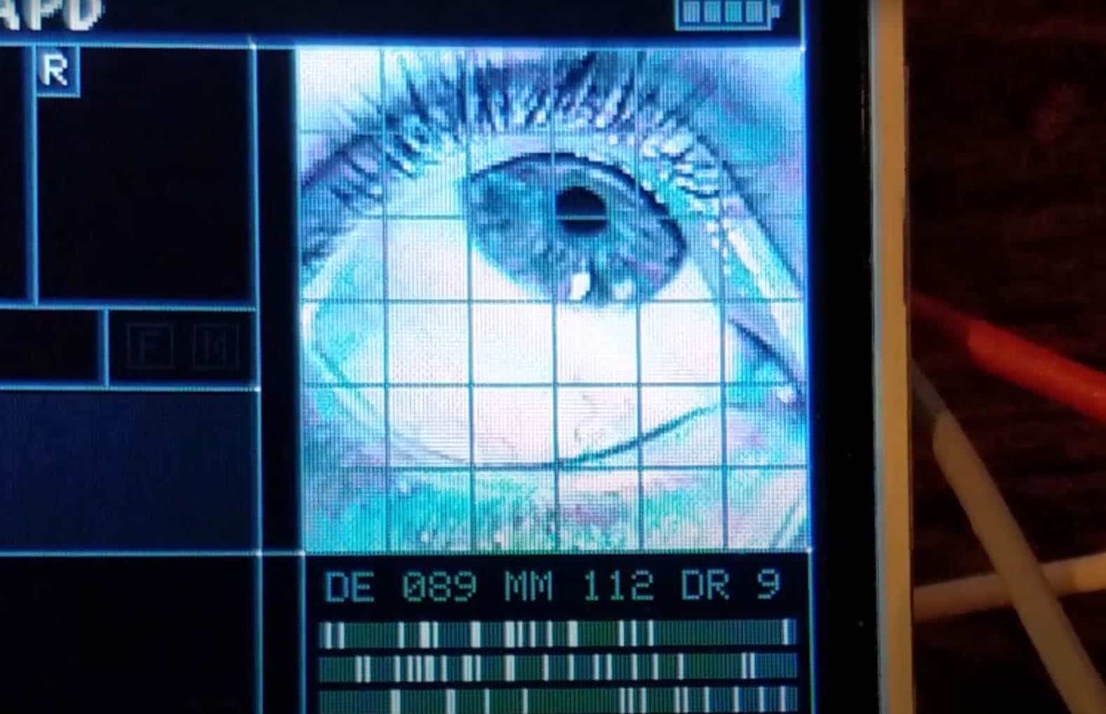
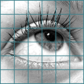
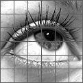
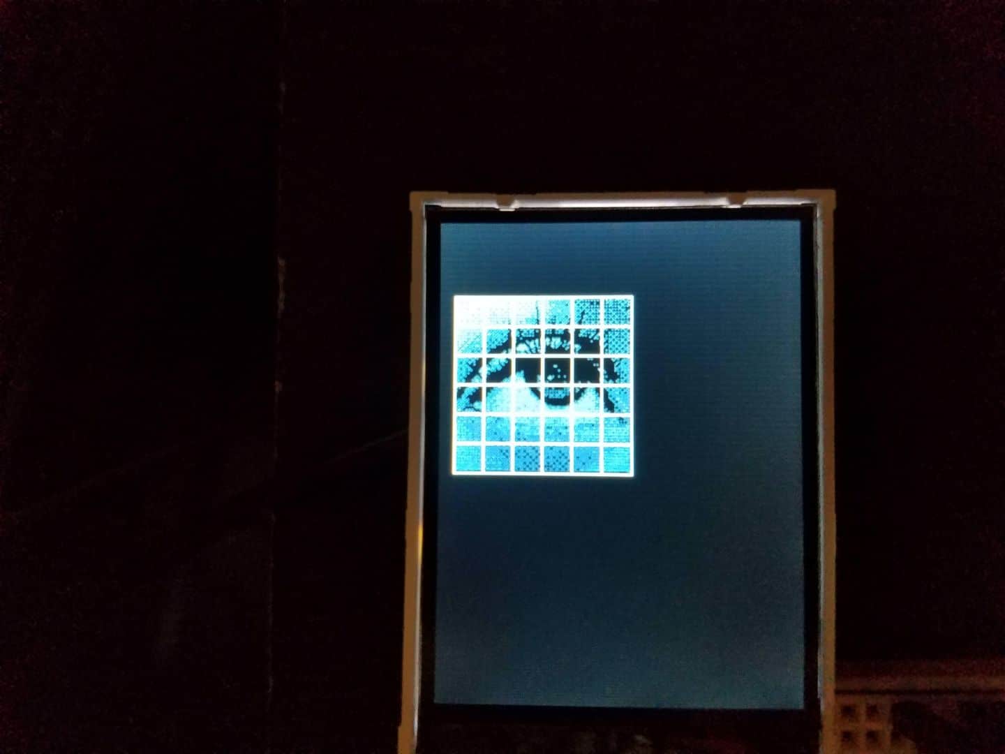
The best answer I have is that we draw it all by hand using our various graphics primitives functions. It’s difficult and tedious, but it also takes the absolute least amount of memory on the arduino. To highlight an example, I’m going to use this grid design with an eye.
Simple enough, right? The TFT graphics libraries can draw bitmaps. But wait – a 24-bit bitmap like this takes 44,100 bytes to store. This is far more than the 28672 the entire device has available, and that’s just for a 121×121 pixel image to display on a 240×320 pixel screen. Damn. What can we do? Well, we can lose color data completely. Take it to grayscale. Save it as an 8-bit bitmap.
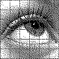
That knocks us down to 15928 bytes. Enough to get in memory? Sure. But enough to get in memory and do anything else useful? Not really. What if we go all the way down to monochrome? A 1-bit bitmap – pixels are either on or off (black or white). Photoshop (or similar programs) have dithering algorithms to try and process this change in a sensible way. What are we working with then?
We’re down to 2000 bytes. That’s far more manageable, isn’t it? Maybe a bit rough looking, but fortunately the tech we’re seeing in Blade Runner 2049 still has some analog flairs that suggest that maybe we can get away with this. The graphics functions that draw this out on the screen can accept color parameters, so you can print the entire image in whatever color you want:
tft.drawLine(startX,startY,endX,endY,COLOR);
tft.drawLine(startX,startY,endX,endY,COLOR);
tft.drawLine(startX,startY,endX,endY,COLOR);
tft.drawLine(startX,startY,endX,endY,COLOR);

... and so on.
This works, but these kind of line-by-line declarations are not exactly memory-efficient in terms of space on the Arduino. We can do better. We can, in fact, utilize the tft.drawRect() method to draw some rectangles, and set a quick function up to run through the logic of drawing 49 separate, offset rectangles:
void drawEyeGrid(int xPos, int yPos, int16_t color){
//set up initial grid - iterative rectangles, 6x6
for(int y = 0; y<6; y++){
for(int x = 0; x<6; x++){
tft.drawRect(xPos+20*x,yPos+20*y,21,21,color);
}
}
//highlight each corner with a white pixel for aesthetics
for(int y = 0; y <= 6; y++){
for(int x = 0; x <= 6; x++){
tft.drawPixel(xPos+20*x, yPos+20*y, WHITE);
}
}
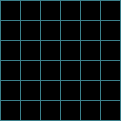
} So that when we call a functon – drawEyeGrid(10, 50, MEDBLUEUI); – it draws our grid out in near-instant fashion (MEDBLUEUI here is just a color value I declared in advance). I set it up with an X and Y coordinate variable so we can move the grid around on the screen to wherever we may ultimately want it.
Great. Now how do we get the eye to show underneath that? The first step is to take our monochrome image and convert it to a byte array. That sounds complicated, but it actually isn’t – there’s a great online tool for exactly this. We upload our image, ask it for arduino-format code, and like magic, it takes our graphic and figures out a suitable byte array.
const unsigned char eyeGraphic [] PROGMEM = {
    0x57, 0x7f, 0x7f, 0xff, 0xff, 0xff, 0x77, 0x55, 0x55, 0x55, 0x55, 0x55, 0x55, 0x55, 0x55, 0xff, 0xff, 0xff, 0xff, 0xff, 0xff, 0xff, 0xff, 0x77, 0x54, 0x44, 0x00, 0x02, 0x45, 0x45, 0x7f, 0xff,
    0xff, 0xff, 0xff, 0xff, 0xfd, 0x75, 0x55, 0x55, 0x55, 0x55, 0x55, 0x55, 0x57, 0xff, 0xff, 0xff, 0xff, 0xff, 0xff, 0xf7, 0xfd, 0x55, 0x54, 0x40, 0x00, 0x05, 0x04, 0x57, 0x77, 0xff, 0xff, 0xff,
    0x77, 0x77, 0x75, 0x55, 0x55, 0x55, 0x55, 0x11, 0x55, 0x55, 0x5f, 0xff, 0xff, 0xff, 0xff, 0xff, 0xff, 0xdf, 0x77, 0x54, 0x44, 0x44, 0x00, 0x04, 0x04, 0x7f, 0xff, 0xff, 0xff, 0xff, 0xff, 0x77,
    0xd5, 0x55, 0x55, 0x55, 0x55, 0x55, 0x55, 0x55, 0x7f, 0xff, 0xff, 0xff, 0xff, 0xff, 0xff, 0x3f, 0xf5, 0x55, 0x54, 0x40, 0x00, 0x00, 0x40, 0x7f, 0x7f, 0x7f, 0x77, 0x77, 0xf7, 0x77, 0x55, 0x55,
    0x55, 0x55, 0x55, 0x55, 0x55, 0x51, 0xff, 0xff, 0xff, 0xff, 0xff, 0xff, 0xfe, 0x77, 0x57, 0x54, 0x44, 0x44, 0x44, 0x40, 0x47, 0xff, 0xff, 0xff, 0x7f, 0x5f, 0xff, 0x55, 0x55, 0x55, 0x55, 0x51,
    0x55, 0x55, 0x55, 0x57, 0xff, 0xff, 0xff, 0xff, 0xff, 0xff, 0xf9, 0xf7, 0x55, 0x51, 0x40, 0x40, 0x40, 0x40, 0x5f, 0xff, 0x77, 0x75, 0x77, 0x75, 0x57, 0x55, 0x55, 0x55, 0x45, 0x45, 0x55, 0x55,
    0x55, 0x5f, 0xff, 0xff, 0xff, 0xff, 0xff, 0xff, 0x67, 0x74, 0x54, 0x54, 0x14, 0x44, 0x44, 0x44, 0x7f, 0xff, 0x77, 0x55, 0x55, 0xd5, 0x55, 0x55, 0x55, 0x55, 0x15, 0x15, 0x55, 0x55, 0x55, 0x7f,
    0xff, 0xff, 0xff, 0xfd, 0x7f, 0xd5, 0x15, 0x41, 0x54, 0x54, 0x40, 0x00, 0x04, 0x00, 0x77, 0x77, 0x57, 0x57, 0x55, 0x55, 0x55, 0x15, 0x55, 0x55, 0x51, 0x55, 0x55, 0x55, 0x55, 0xff, 0xff, 0xff,
    0xf7, 0x77, 0x77, 0x54, 0x54, 0x04, 0x50, 0x40, 0x44, 0x44, 0x44, 0x47, 0xfd, 0x75, 0x55, 0x55, 0x45, 0x55, 0x54, 0x55, 0x15, 0x45, 0x45, 0x55, 0x15, 0x55, 0x57, 0xff, 0xff, 0xff, 0xff, 0xd4,
    0x55, 0x41, 0x55, 0x35, 0x05, 0x00, 0x00, 0x40, 0x40, 0x4f, 0x77, 0x55, 0x55, 0x55, 0x15, 0x55, 0x51, 0x54, 0x55, 0x14, 0x15, 0x54, 0x55, 0x55, 0x5f, 0xff, 0xf7, 0xf7, 0x76, 0x74, 0x44, 0x00,
    0x40, 0x44, 0x40, 0x04, 0x40, 0x40, 0x44, 0x55, 0x55, 0x55, 0x55, 0x54, 0x51, 0x55, 0x05, 0x51, 0x50, 0x50, 0x55, 0x45, 0x45, 0x55, 0x7f, 0xff, 0xf7, 0x55, 0x54, 0x50, 0x44, 0x40, 0x00, 0x41,
    0x41, 0x40, 0x00, 0x00, 0x04, 0x75, 0x55, 0x55, 0x55, 0x51, 0x51, 0x54, 0x05, 0x45, 0x41, 0x01, 0x55, 0x14, 0x55, 0x55, 0xff, 0x77, 0x77, 0x54, 0x42, 0x44, 0x00, 0x00, 0x00, 0x00, 0x04, 0x04,
    0x40, 0x44, 0x45, 0x55, 0x55, 0x55, 0x55, 0x45, 0x45, 0x50, 0x00, 0x00, 0x00, 0x15, 0x11, 0x45, 0x55, 0x57, 0xff, 0xf5, 0x55, 0x54, 0x04, 0x00, 0x00, 0x00, 0x00, 0x00, 0x00, 0x44, 0x00, 0x40,
    0x55, 0x55, 0x55, 0x55, 0x55, 0x04, 0x40, 0x01, 0x11, 0x50, 0x00, 0x00, 0x14, 0x55, 0x55, 0x5f, 0xf7, 0x75, 0x44, 0x44, 0x00, 0x00, 0x13, 0x73, 0x60, 0x00, 0x00, 0x00, 0x44, 0x44, 0x55, 0x55,
    0x55, 0x55, 0x50, 0x10, 0x11, 0x67, 0x45, 0xc4, 0x40, 0x01, 0x05, 0x15, 0x55, 0x5f, 0x75, 0x54, 0x44, 0x00, 0x00, 0x16, 0x4e, 0xdb, 0x41, 0x00, 0x00, 0x04, 0x04, 0x44, 0x55, 0x55, 0x55, 0x55,
    0x00, 0x05, 0x1c, 0x9d, 0x15, 0x14, 0x00, 0x00, 0x11, 0x55, 0x55, 0x77, 0x57, 0x44, 0x40, 0x00, 0x1f, 0x1d, 0x18, 0x64, 0x40, 0x70, 0x00, 0x04, 0x44, 0x45, 0x55, 0x55, 0x55, 0x40, 0x00, 0x7f,
    0x31, 0x50, 0x50, 0x11, 0x50, 0x00, 0x11, 0x55, 0x57, 0x75, 0x54, 0x40, 0x00, 0x01, 0xff, 0x10, 0x40, 0x00, 0x40, 0x40, 0x00, 0x00, 0x44, 0x55, 0x55, 0x55, 0x50, 0x00, 0x51, 0xf4, 0x45, 0x40,
    0x00, 0x01, 0x00, 0x00, 0x15, 0x55, 0x57, 0x54, 0x44, 0x40, 0x04, 0x40, 0x44, 0x44, 0x00, 0x00, 0x00, 0x00, 0x00, 0x04, 0x44, 0x55, 0x55, 0x55, 0x00, 0x11, 0x45, 0x44, 0x00, 0x00, 0x00, 0x14,
    0x00, 0x00, 0x55, 0x55, 0x55, 0x54, 0x40, 0x00, 0x72, 0x81, 0x40, 0x00, 0x00, 0x00, 0x00, 0x00, 0x00, 0x00, 0x54, 0x55, 0x55, 0x40, 0x01, 0x64, 0x00, 0x40, 0x00, 0x00, 0x00, 0x00, 0x40, 0x04,
    0x05, 0x55, 0x54, 0x44, 0x00, 0x17, 0xcc, 0x00, 0x00, 0x00, 0x00, 0x00, 0x00, 0x00, 0x00, 0x04, 0x05, 0x55, 0x54, 0x00, 0x55, 0x04, 0x00, 0x00, 0x00, 0x00, 0x00, 0x00, 0x50, 0x00, 0x54, 0x55,
    0x54, 0x40, 0x01, 0x6f, 0x00, 0x00, 0x00, 0x00, 0x00, 0x00, 0x00, 0x00, 0x00, 0x41, 0x55, 0x55, 0x40, 0x05, 0x55, 0x00, 0x00, 0x00, 0x00, 0x00, 0x00, 0x00, 0x00, 0x00, 0x15, 0x54, 0x44, 0x00,
    0x17, 0x90, 0x00, 0x00, 0x00, 0x00, 0x00, 0x00, 0x00, 0x00, 0x00, 0x44, 0x55, 0x41, 0x00, 0x15, 0x10, 0x00, 0x00, 0x00, 0x00, 0x00, 0x00, 0x00, 0x50, 0x01, 0x15, 0x55, 0x40, 0x05, 0x15, 0x00,
    0x00, 0x00, 0x00, 0x06, 0x00, 0x00, 0x00, 0x00, 0x00, 0x55, 0x55, 0x40, 0x15, 0x55, 0x00, 0x00, 0x00, 0x00, 0x00, 0x00, 0x00, 0x00, 0x00, 0x05, 0x54, 0x44, 0x40, 0x7f, 0x44, 0x00, 0x00, 0x00,
    0x00, 0x00, 0x00, 0x00, 0x00, 0x40, 0x04, 0x55, 0x55, 0x41, 0x51, 0x40, 0x00, 0x00, 0x00, 0x00, 0x04, 0x00, 0x00, 0x00, 0x50, 0x15, 0x55, 0x50, 0x03, 0x70, 0x00, 0x00, 0x10, 0x00, 0x00, 0x00,
    0x00, 0x00, 0x00, 0x50, 0x00, 0x55, 0x54, 0x01, 0x50, 0x00, 0x01, 0x40, 0x00, 0x00, 0x00, 0x00, 0x00, 0x00, 0x00, 0x15, 0x54, 0x40, 0x04, 0x00, 0x00, 0x05, 0x40, 0x00, 0x00, 0x00, 0x00, 0x00,
    0x00, 0x00, 0x04, 0x55, 0x40, 0x45, 0x00, 0x00, 0x55, 0x00, 0x14, 0x14, 0x44, 0x00, 0x00, 0x01, 0x40, 0x15, 0x54, 0x01, 0x40, 0x00, 0x01, 0x7f, 0x00, 0x10, 0x70, 0x00, 0x00, 0x00, 0x00, 0x00,
    0x05, 0x54, 0x05, 0x40, 0x00, 0x15, 0x57, 0x00, 0x50, 0x40, 0x00, 0x00, 0x00, 0x14, 0x01, 0x54, 0x44, 0x17, 0x40, 0x00, 0x57, 0x7e, 0x00, 0x00, 0x00, 0x00, 0x00, 0x00, 0x04, 0x44, 0x45, 0x50,
    0x15, 0x00, 0x01, 0x55, 0x7c, 0x01, 0x54, 0x00, 0x44, 0x10, 0x40, 0x05, 0x45, 0x54, 0x00, 0x44, 0x00, 0x05, 0xff, 0xfc, 0x01, 0x00, 0x00, 0x00, 0x00, 0x40, 0x01, 0x01, 0x55, 0x01, 0x40, 0x00,
    0x15, 0x57, 0x74, 0x05, 0x40, 0x00, 0x40, 0x01, 0x40, 0x45, 0x45, 0x44, 0x07, 0x40, 0x00, 0x77, 0xff, 0xf8, 0x00, 0x00, 0x00, 0x00, 0x41, 0x40, 0x44, 0x44, 0x54, 0x15, 0x40, 0x05, 0x55, 0x7f,
    0xd8, 0x15, 0x44, 0x05, 0x44, 0x05, 0x40, 0x55, 0x55, 0x40, 0x54, 0x00, 0x05, 0x7f, 0xff, 0xf8, 0x10, 0x00, 0x01, 0x04, 0x1f, 0x00, 0x45, 0x45, 0x41, 0x54, 0x00, 0x55, 0x77, 0x77, 0xf0, 0x15,
    0x55, 0x55, 0x10, 0x55, 0x00, 0x55, 0x54, 0x01, 0x40, 0x00, 0x57, 0xff, 0xff, 0xf0, 0x00, 0x01, 0x00, 0x00, 0x7e, 0x00, 0x56, 0x44, 0x05, 0x40, 0x05, 0x55, 0x77, 0xff, 0xd0, 0x15, 0x55, 0x50,
    0x05, 0x75, 0x01, 0x55, 0x50, 0x14, 0x00, 0x05, 0x7f, 0xff, 0xff, 0xf0, 0x11, 0x11, 0x00, 0x07, 0xfc, 0x00, 0x55, 0x50, 0x50, 0x00, 0x15, 0x77, 0x7f, 0xff, 0xd0, 0x05, 0x54, 0x00, 0x17, 0x74,
    0x05, 0x55, 0x40, 0x40, 0x00, 0x57, 0xff, 0xff, 0xff, 0xf0, 0x00, 0x00, 0x00, 0x7f, 0xf4, 0x04, 0x75, 0x45, 0x50, 0x01, 0x55, 0x57, 0x7f, 0xff, 0xd0, 0x00, 0x00, 0x01, 0x7f, 0x54, 0x05, 0x55,
    0x15, 0x40, 0x05, 0x77, 0xff, 0xff, 0xff, 0xf8, 0x00, 0x00, 0x17, 0xff, 0xf4, 0x04, 0x75, 0x55, 0x41, 0x55, 0x57, 0x77, 0xff, 0xff, 0xd4, 0x00, 0x00, 0x57, 0xff, 0x54, 0x05, 0x55, 0x54, 0x07,
    0x57, 0x7f, 0xff, 0xff, 0xff, 0xfc, 0x00, 0x03, 0xff, 0xff, 0x50, 0x05, 0x75, 0x55, 0x55, 0x55, 0x57, 0xff, 0xfd, 0xfd, 0xdd, 0x00, 0x15, 0xff, 0xfd, 0x50, 0x15, 0x55, 0x50, 0x1f, 0x5d, 0xff,
    0xff, 0xff, 0xff, 0xfd, 0xdd, 0xff, 0xff, 0xff, 0x40, 0x05, 0x75, 0x40, 0x15, 0x55, 0x77, 0x77, 0x7f, 0xff, 0xfd, 0x55, 0xff, 0xff, 0x75, 0x50, 0x55, 0x47, 0x15, 0x04, 0x77, 0xff, 0xff, 0xff,
    0xff, 0xff, 0xff, 0xff, 0xff, 0xff, 0x40, 0x47, 0x55, 0x55, 0x01, 0x55, 0x55, 0x77, 0xff, 0x77, 0xff, 0xff, 0xff, 0xff, 0x75, 0x51, 0x55, 0x51, 0x55, 0x40, 0x5f, 0xff, 0xff, 0xff, 0xff, 0xff,
    0xff, 0xff, 0xff, 0xf7, 0x40, 0x07, 0x55, 0x55, 0x75, 0x57, 0x77, 0x77, 0x77, 0x77, 0x77, 0x77, 0x7f, 0x77, 0x55, 0x54, 0x55, 0x57, 0x57, 0x74, 0x5f, 0xff, 0xff, 0xff, 0xff, 0xff, 0xff, 0xff,
    0xff, 0x77, 0x54, 0x55, 0x55, 0x55, 0x55, 0x55, 0xd5, 0x77, 0x75, 0x55, 0x55, 0x7f, 0xfd, 0xfd, 0x55, 0x54, 0x55, 0x75, 0x75, 0x5f, 0x45, 0xff, 0xff, 0xff, 0xff, 0xff, 0xff, 0xff, 0xff, 0xf5,
    0xf0, 0x55, 0x55, 0x55, 0x55, 0x55, 0x7f, 0x77, 0x57, 0x75, 0x57, 0x77, 0x77, 0x75, 0x55, 0x55, 0x57, 0x76, 0x77, 0x76, 0x57, 0x7f, 0xff, 0x7f, 0xff, 0x7f, 0xff, 0xff, 0xf7, 0x77, 0x60, 0x55,
    0x55, 0x55, 0x55, 0x55, 0x55, 0x7d, 0x75, 0x55, 0x57, 0xff, 0x55, 0x55, 0x55, 0x55, 0x7f, 0x55, 0x57, 0x57, 0xff, 0x55, 0x5f, 0xff, 0xff, 0xff, 0xfd, 0x54, 0x57, 0x77, 0x57, 0x55, 0x55, 0x55,
    0x57, 0x75, 0x55, 0x55, 0x55, 0x55, 0x55, 0x55, 0x55, 0x55, 0x55, 0x57, 0xff, 0x55, 0x57, 0x57, 0x5d, 0xf7, 0xf5, 0xc4, 0x35, 0x46, 0x75, 0xf7, 0x7f, 0xff, 0xfd, 0x55, 0x55, 0x55, 0x55, 0x57,
    0xd5, 0xd5, 0xd5, 0x57, 0x5d, 0x55, 0x55, 0x75, 0x77, 0x7f, 0xff, 0x55, 0x55, 0xd7, 0xdf, 0x7f, 0xfd, 0xdf, 0xd7, 0xff, 0x7f, 0xff, 0xff, 0xff, 0xf7, 0x55, 0x55, 0x55, 0x55, 0x55, 0x55, 0x57,
    0x57, 0x55, 0x57, 0x77, 0x75, 0x57, 0x77, 0x7f, 0xf7, 0x74, 0x54, 0x57, 0x74, 0x5f, 0x7f, 0x4d, 0x47, 0x7f, 0x7f, 0xff, 0xff, 0xff, 0xf5, 0x55, 0x55, 0x55, 0x55, 0x55, 0x55, 0x55, 0x55, 0x55,
    0x55, 0x55, 0x55, 0x55, 0x55, 0x7f, 0xfd, 0x55, 0x55, 0x55, 0x55, 0x75, 0x55, 0x55, 0x55, 0xfd, 0xff, 0xff, 0xff, 0xff, 0x77, 0x55, 0x55, 0x55, 0x55, 0x55, 0x55, 0x55, 0x55, 0x55, 0x55, 0x55,
    0x55, 0x55, 0x55, 0xff, 0x77, 0x57, 0x54, 0x54, 0x44, 0x55, 0x47, 0x77, 0x55, 0x77, 0x77, 0x77, 0x77, 0x75, 0x55, 0x55, 0x55, 0x55, 0x55, 0x55, 0x55, 0x55, 0x55, 0x55, 0x55, 0x55, 0x55, 0x55,
    0x57, 0xff, 0xfd, 0x55, 0x50, 0x54, 0x54, 0x45, 0x55, 0x55, 0x55, 0x57, 0x55, 0x55, 0x77, 0x77, 0x75, 0x55, 0x55, 0x55, 0x55, 0x55, 0x55, 0x55, 0x55, 0x55, 0x55, 0x55, 0x55, 0x55, 0x7f, 0xff,
    0x77, 0x54, 0x44, 0x44, 0x44, 0x45, 0x44, 0x54, 0x57, 0x75, 0x57, 0x77, 0x77, 0xf7, 0x55, 0x55, 0x55, 0x55, 0x55, 0x55, 0x55, 0x55, 0x55, 0x55, 0x55, 0x55, 0x55, 0x55, 0xff, 0xff, 0x75, 0x55,
    0x55, 0x55, 0x54, 0x55, 0x45, 0x55, 0x55, 0x55, 0x55, 0x57, 0xff, 0x77, 0x55, 0x55, 0x55, 0x55, 0x55, 0x55, 0x55, 0x55, 0x55, 0x55, 0x55, 0x55, 0x55, 0x77, 0xff, 0xff, 0x77, 0x54, 0x44, 0x44,
    0x54, 0x45, 0x54, 0x57, 0x55, 0x57, 0x57, 0x7f, 0xff, 0x75, 0x55, 0x55, 0x55, 0x55, 0x55, 0x55, 0x55, 0x55, 0x55, 0x55, 0x55, 0x55, 0x55, 0x77, 0xff, 0xff, 0x55, 0x54, 0x54, 0x54, 0x54, 0x55,
    0x54, 0x55, 0x55, 0x55, 0x7f, 0xff, 0xf7, 0x75, 0x55, 0x55, 0x55, 0x55, 0x55, 0x55, 0x55, 0x55, 0x55, 0x55, 0x55, 0x55, 0x77, 0x7f, 0xff, 0x77, 0x77, 0x54, 0x44, 0x44, 0x44, 0x44, 0x44, 0x44,
    0x54, 0x57, 0x7f, 0xff, 0xf5, 0x75, 0x55, 0x55, 0x55, 0x55, 0x55, 0x55, 0x55, 0x55, 0x55, 0x55, 0x55, 0x57, 0xf7, 0x7f, 0xff, 0xff, 0x75, 0x55, 0x55, 0x54, 0x55, 0x54, 0x54, 0x55, 0x55, 0x5f,
    0xff, 0xff, 0x77, 0x55, 0x55, 0x55, 0x55, 0x55, 0x55, 0x55, 0x55, 0x55, 0x55, 0x55, 0x57, 0x7f, 0x75, 0xff, 0xff, 0x77, 0x77, 0x54, 0x54, 0x44, 0x44, 0x44, 0x44, 0x54, 0x57, 0x7f, 0xff, 0xff,
    0x7d, 0x75, 0x55, 0x55, 0x55, 0x55, 0x55, 0x55, 0x55, 0x55, 0x55, 0x55, 0x55, 0xf5, 0x77, 0xff, 0xff, 0x75, 0x75, 0x55, 0x54, 0x54, 0x40, 0x54, 0x55, 0x55, 0x7f, 0xff, 0xff, 0xf7, 0x77, 0x75,
    0x55, 0x55, 0x55, 0x55, 0x55, 0x55, 0x55, 0x55, 0x55, 0x57, 0x77, 0x57, 0x7f, 0xff, 0xff, 0x77, 0x75, 0x54, 0x44, 0x44, 0x44, 0x44, 0x44, 0x77, 0xff, 0xff, 0xff, 0xff, 0x77, 0x55, 0x55, 0x55,
    0x55, 0x55, 0x55, 0x55, 0x55, 0x55, 0x55, 0x55, 0x55, 0x5d, 0xf
};
I know this looks like a mess, but if you’d believe it, the whole thing takes ~1,800 bytes to draw. We need to set up a function that can parse this information, which I am basically stealing wholesale from the Adafruit GFX library – it reads the byte array, and based on the information contained in it uses the drawPixel() function at the X-Y coordinates of each pixel in the bitmap.
void drawBitmap(int16_t x, int16_t y, const uint8_t *bitmap, int16_t w, int16_t h, uint16_t color) {
  int16_t i, j, byteWidth = (w + 7) / 8;
  uint8_t byte;
  for(j=0; j<h; j++) {
    for(i=0; i<w; i++) {
      if(i & 7) byte <<= 1;
      else      byte   = pgm_read_byte(bitmap + j * byteWidth + i / 8);
      if(byte & 0x80) tft.drawPixel(x+i, y+j, color);
    }
  }
}
Note that you can set the color of the bitmap as it draws, so we can combine all of this into the following lines:
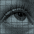
drawBitmap(10,50,eyeGraphic,120,119,MEDBLUEUI);
drawEyeGrid(10, 50, WHITE);
Which produces our goal!
We can go a step or two further here if we want to. We can, for example, color the sclera of the eye white with a separate byte array, or color the pupil whatever color we want with yet another byte array. These are small and light enough in terms of memory that it’s negligible in terms of the overall arduino program.
WHAT DOES THIS ALL MEAN?
In the interest of draw speed and memory efficiency, I will be hard-coding the visuals the display shows to the micro-controller, rather than loading them from external memory sources. This directs some of the design philosophy of the graphics themselves, because I will need to basically partition everything in terms of element and color. There’s not going to be any anti-aliasing or shading on the graphics beyond halftone patterns because I can’t spare the overhead for it, but in some ways I feel like that aids the aesthetics of this particular item.
It also means that once I start committing to a certain UI or display design, I have to really commit, because changing things down the line might require fully overhauling the code from the bottom up. Which brings me to the present, where I’m agonizing over what the UI for this thing should actually look like!
FIGHTING WITH THE DESIGN
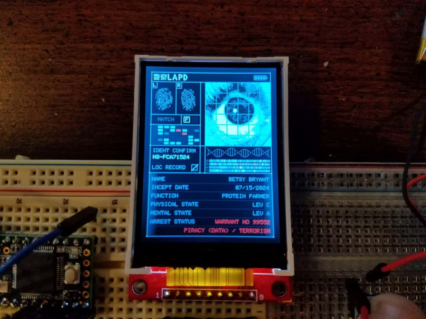
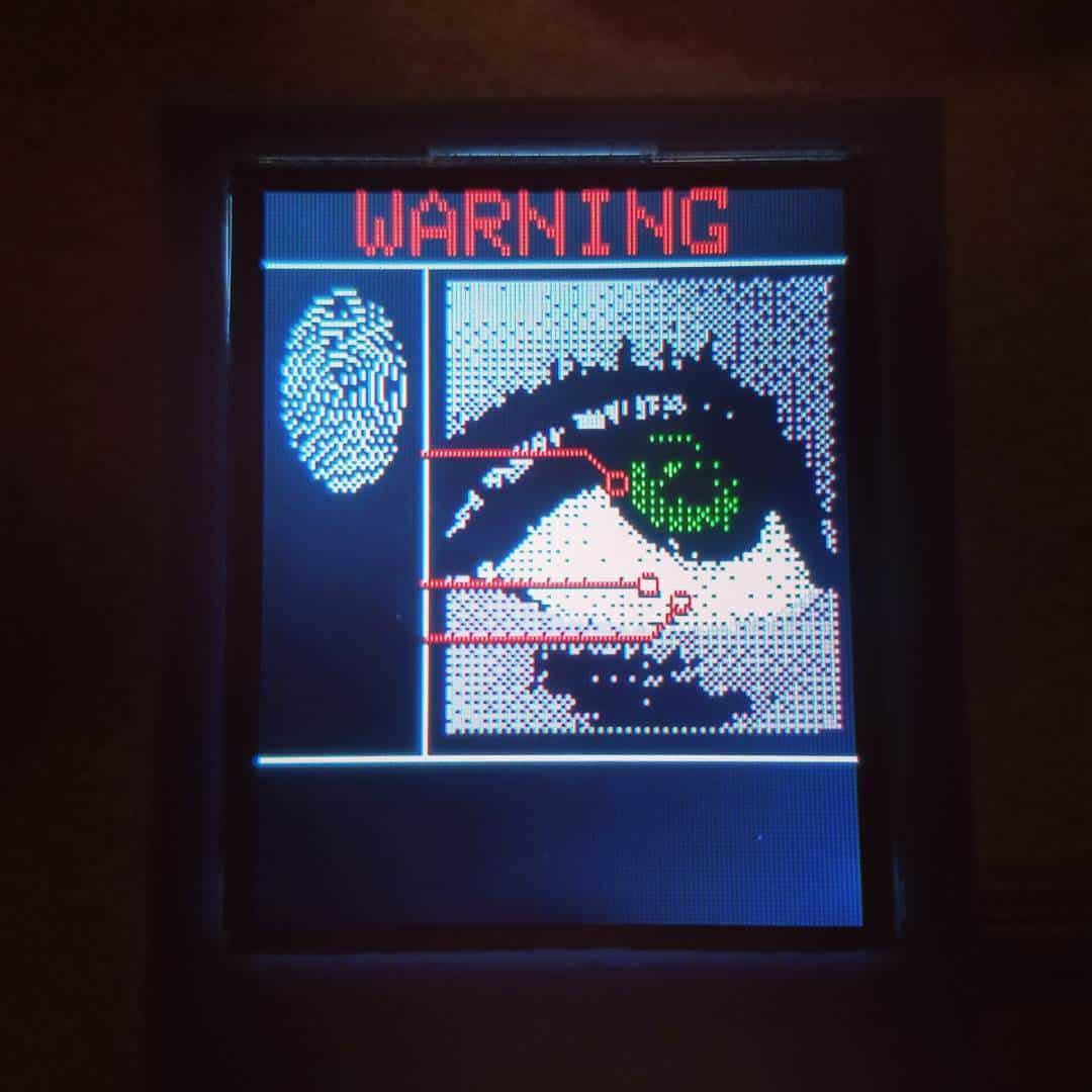
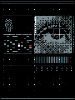
This is my current mock-up. I’m trying to stick to a generalized scheme of blues, maybe a bit tan, with white and red for detail spots at the moment. I liked the look of the white grid of dots as a backdrop. I can make all sorts of tech-looking greeblies, but I think my real issue is I don’t know what to fill the spaces up with that feels appropriate. For example, is a DNA helix silly? Probably not, given the context of the scanner, but it does feel a bit hokey.
I also played around with a “startup screen”, but I’m not really sold on it yet. Feels a bit too 80s-Encarta-y to me. It probably would have worked for the original Blade Runner’s aesthetic of 2019 (a.k.a. 80s as hell) but 2049 looks a bit more minimalist and modern to me.
Candidly, I don’t feel like I’m great at UI design. Not really my niche. I’d love some input or feedback. I want to work the design out fully before I start getting in and coding it all together so that I don’t end up redoing it a million times over. I don’t feel like I’m getting a good “Blade Runner” aesthetic for this yet – more generic futuristic UI than anything. Looking at the Creativereview.co.uk article in particular, I think I have to back up and maybe try again from scratch to get the look right.